Victor's Journal
18 November 2008: I'm pretty tired
Well the deadline for the paper and all materials is tomorrow. I handed everything in yesterday, which certainly attracted the ire of my research teacher. I'm done but certainly there's still more work to revisit in this project. Certainly I can look back and say that I shouldn't have pushed writing the paper until November but I was able to put in some new things because of it. As for the paper itself, I think I present my information clearly. At the beginning of the process, it was so hard to picture the entire paper that I didn't know where to begin. I am still glad to have the experience at the high school level of writing a paper.
I've never done an all-nighter before but I did one to finish this paper; if procrastination were illegal, I'd probably be in jail for it. I was surprised, as was my body system, to find the day continuing, with with no sleep in between. I sat in front of my computer all night, eeking out my paper. Energy drinks are unhealthy and so I chewed spearmint Orbit gum and drank green tea; chewing gum is almost like smoking cigarettes sometimes. The tea warmed me up but I had steeped the leaves so many times that I might as well have been drinking hot water. I'm in running shorts and t-shirt because I didn't bother to change out of them after my run the day before. I write my paper; it's 6:30 AM or so, and I finish and I am freezing. I run upstairs to my bathroom where I soak in a shower; but a few minutes of hot water hardly doesn't warm my body. I get out of the shower and I realize, with toothbrush and Crest toothpaste in my mouth, it's just like waking up everyday, only the day just ended a few minutes ago. I stumbled around school that day. Strangely though, the tiredness doesn't hit until late evening. Today, I'm still pretty tired. It was not just an intellectual experience but a physical experience. I promise to myself there will be less procrastination in the future.
7 November 2008: More measurements taken and paper
A few days ago, Dr. Noe and I made measurements of the laser behavior in open-loop mode. The results were very interesting: the response of the laser mirrors the change in heater power, which was expected. As heater power increases, the length of the laser should increase and cause the light signal measured from the laser to change. As the frequency of the sine wave sent into the frequency generator changed however, the phase shift between the heater power and the laser output seemed to remain around pi/2. I'm not quite sure what to make of it and so far I've only found a few cryptic lines in one paper that refers to a heat pulse sent by the heater into the glass laser tube. This heat pulse causes an immediate expansion at the surface but the expansion of the whole thickness of the tube takes a longer time.
I will be writing my paper in the next few days and it should be interesting to see if I survive or not.
2 November 2008: Enhanced Measuring Setup
At this point in time, I am still taking measurements of my stabilized laser. Four wires now snake their way across the gray floor of the LTC and terminate at the data acquisition device. There are four signals: error signal (from circuit), photodetector signal (photocurrent converted to voltage), function generator signal, and gate voltage signal. The function generator I plan to use to make open-loop measurements of the laser system. That is, I plan to adjust the heater to reach thermal equilibrium with a mode captured at the centered of the gain curve. Then I will use the function generator to send a sine wave voltage onto the gate so that heater power will oscillate around the level of heat needed to reach thermal equilibrium. The data acquisition device will acquire data from the circuit.I need to work out some of the technical details of sending the function generator signal into the circuit without affecting the heater levels
I need to have a paper very soon. I have always been looking at sources but writing my first 20 pages of research seems a monumental task to me. I've started to study the language of LaTeX. Sure it's not necessary to write a paper but I always imagined writing a paper in LaTeX. It's good to learn another form of computer language and text in LaTeX looks so good for some reason; it has to be those computer modern fonts.
25 October 2008:
19 October 2008: Direction
Maybe it's me, maybe it's just the way research is, but I feel myself being pulled in several directions. Other than schoolwork, which is always there, there's several things I still need to do. Write, read articles, measure the heater response, and still optimize the circuit the best I can. A frustrating thing is that sometimes the circuit works well and then the laser begins to flicker, ruining my measurement. The flickering laser has been a problem since I first had the laser. I've tried various ways of securing the power supply connection to the laser tube but everything I tried seems not to work. The laser is a moody thing, at times operating perfectly for hours but at other times, it flickers, making a sound similar to elecrical arcing and disrupting all measurement.
13 October 2008: The results
Today Dr. Noe and I had a long discussion about my project. Aspects included the effect of an imperfect beam spliter and the graph of the error signal. It should be possible to measure frequency in a similar way as previously mentioned with the error signal instead of mode sweeping curve. Because the error signal is the difference between two signals, it should be less affected by changes in intensity so a closer measure of the frequency stability can be obtained. In addition, it would be useful to measure the delay time between mode position and heater level, a transfer function for the heater and laser.
I checked back on my laser measurement from the other day from the next morning and I saw a very curious result. The output from the laser when I left it seemed really steady on the monitoring device but over the course of several hours, it had produced an oscillating pattern. The output was centered around a value and the intensity oscillation period was on the value of hours. If one looked at stability over a shorter period of time, such as one hour at a bottom or top of the long oscillation cycle, the stability was even better. This type of oscillation is a promising sign because it is either something that can be improved upon (since it seems more organized) or it's something in the room (temperature?) that is causing the oscillation.
10 October 2008: Improving the circuit
I added a integrative and derivative component to see if I could improve my circuit. Adding the differentiator alone did not result in much improvement but adding the integrator did. I did it again, I just hooked up the circuit together without paying much mind to values. I mean I did read about PID control and how one method advised tuning the proportional component until the thing one tried to stabilize, ie the laser intensity and frequency, went into ringing (oscillation). Then the method advised halving that proportional value and then adjusting integral and derivative components based on that. Well I don't know what I did, but apparently it worked, and it was really stable. I was really shocked and the only thing I could think of was taking a measurement with the computer device. Since it was getting late, I let it run.
2 October 2008: Long stability measurement
I found that my new circuit was also capable of keeping the laser modes stabilized for a long time. But like the previous circuit, there is erratic long term drift. The overall stability is not better than the previous circuit, although I understand it better.
1 October 2008: The stabilization in action
Well, I was very wrong. Today, Dr. Noe and I worked with the laser and circuit. There is a switch in the circuit that breaks the connection between the photodiodes and feedback circuitry and the heater itself. With the stabilization off, I set a voltage level on the heater using a potentiometer and set to equilibrium. To my surprise, I could easily control the error signal with manual control of the heater with my potentiometer. I adjusted it so that it was stable when the error signal, which I read with a multimeter, was close to 0. I then turned on the stabilization and it worked. I had thought somehow that the conditions were too voltatile for manual control to bring stability. Perhaps that is true in the long term, but for a short time, one can adjust the heater so that equilibrium is just when the two modes are even. Then, one flips the switch, connecting the feedback circuitry also to the heater. Since the laser is at the equilibrium, the circuit will try to get the feedback circuitry to 0 in order to keep the laser temperature, and therefore the modes, in equilibrium, or stable.
This way of doing it really helped me understand how to choose where on the gain curve the circuitry fixes the modes at.
30 Sepetember 2008: Rebuilt circuit first part
Today I rebuilt the circuit. What's advantageous about this circuit is that there an actual point in the circuit where the voltage measured is the error signal between the two photodiodes. In addition, one should easily be able to control where the modes will be stabilized on the gain curve. The circuit still works off two photodiodes which read the waste beam from the back of the laser. There is a polarizing beam splitter cube in the back. There is a problem that the beam splitter is imperfect and one photodiode receives more light than the other. I have measured the photocurrents coming from both diodes and have taken the halves of their maximums. I used these values to calculator resistor values for the two opamps that transform the current into voltage. It should be that when the two modes are equal, the difference in voltage between the two opamps is 0, representing a 0 error signal.
26 September 2008: PID and frequency measurement
I've mentioned this before. My stabilization circuit has always proportional feedback only. I have tried to put an integrator stage in series after the proportional stage but it never worked for me. The heater seemed to turn on only when the light levels passed a certain level. Then the heater response was too much and made the output overshoot. The heater would completely shut down and the light level would drop again, continuing the oscillatory cycle. I studied PID more closely and am going to build a circuit including integrative and derivative components. I am going to have an adjustable voltage divider setting a setpoint voltage on the MOSFET gate. Once the heater and laesr reach equilibrium with the air temperature, I can turn on the stabilization.
Dr. Noe and I talked today and Dr. Noe had a very interesting idea about measuring the frequency--not intensity--stability of my laser without any measurement equipment. I have before, measured the laser as it warmed up using the computer. The result is an oscillating pattern as the single polarization I am measuring increases in intensity and then drops in intensity as it moves across the gain curve (changing in frequency). The laser tube length determines the difference in frequency between each adjancent mode. In the case of my laser, which is 14.0 cm long, the mode spacing is c/2L or about 1100 MHz. This means that each peak in intensity measured of a single polarization is two modes apart or 2200 MHz. It is two modes apart because between two peaks, an orthagonally polarized mode, which was blocked by the polarizer, passed through the gain curve. Instead of time, I could estimate how stable in frequency my laser was by using the intensity range I measured for my stabilized laser and put its range on the y-axis of the laser warmup measurement. That intensity range corresponds to a certain frequency range according to the warmup curve.
Now there are several assumptions going here. The first is that the laser tube's expansion rate as it warms up is constant. If not, the time scale on the bottom can't be replaced iwth a frequency scale. In addition, it must be verified that each peak is 1,500 MHz wide. Finally, this estimate will be an upper limit, as in the greatest variance in stability, because variations in laser output intensity affect the stability as measured by the photodetector monitoring a single mode.
20 September 2008: The next day
After leaving late last night, I have returned this Saturday morning to take a look at my results. It turns out they were ok. It was the first time I let the stabilization run for such a long time and I was glad to see that the stabilization circuit kept the mode in place all night long. The oscilloscope, when I turned it reported the same -1.0 V on the MOSFET gate that it had when I had left last night. The temperature of the laser tube also did not change by much.
Although the laser remained stabilized, I found that the intensity measurements when graphed on excel did vary slightly with no discernable pattern. It did however stay stable. Given that a single mode of the laser without stabilization produced an intensity reading in volts on the compter ranging from 0 volts to 2.2 volts, the stabilized laser varied around 2.5% of that range over a period of 1 hour. Over the whole length of the measurement however, the intensity variance was a bit greater, more than 5%, when ignoring an anomalous spike that was also in the readings. I don't know what caused the spike, but it does taint the measurement. Perhaps it was a solitary flicker, but here I am, guessing again.
It's been getting really cold to bike back home lately at night. the lab has always been cold. I guess it's time to wear some more clothing
19 September 2008: A long term measurement
Before I reconstruct the circuit I am going to try and get a good idea of this one performs with a stability measurement--monitoring the intensity of one mode with a photodetector connected to the computer over a long time. I know I am monitoring one mode because there is a polarizer in the beam path oriented so that the adjacent orthagonally polarized modes are blocked. The laser tube's length is such that only two (perhaps three if one mode is in the middle of the gain curve) resonant modes can resonate inside the laser tube.
17 September 2008: Going by feel
It's not good to proceed about things using only limited knowledge and intuition. Dr. Noe has suggested that although the circuit works, it's not the ideal way to build a feedback circuit. Instead of me adjusting resistor and thus gain values so that the circuit keeps the laser modes in a point of equilibrium such that the modes are just about even, I will build a different circuit, one that would also be easier to add derivative and integrative components to. I must be more quantitative. Standing and observing my circuit is all well and good but I need more measurements and understanding.
11 September 2008: Mode Sweeping Dark
Dr. Noe is trying to convince me that a certain heating level has a certain equilibrium point and while I believe equilibrium is too easily affected by changing environment conditions. In any case, I have measured warming up curves for the laser. In particular, when I am monitoring one polarization, the beam goes dark every degree celsius or so, demonstrating a generally linear relationship between temperature and tube length.
What is bothersome however is a tendency for the laser to flicker while it is warming up. What I mean by flickering is that the output jumps around and an electrical arcing type of sound is heard. In addition, flicker sometimes causes the polarization modes on the laser to jump, which makes taking measurements difficult. I have tried various methods to solve the flickering including adding a ballast resistor and changing and resecuring the electrical leads multiple times. The flicker is probably the result of increased distance from the power supply to the laser coupled by thermal expansion as the laser heats up, which may weaken the connection, which is a metal clamp on the laser head.
4 September 2008: Measured
Today I got the measurement properly that I missed yesterday. What I use a Measurement Computer USB-1208LS device which reads voltages and sends them to the computer. I can measure current like one would wiht a photodetector, by putting a resistor across the leads to the measurement device so that I am measuring a voltage, which will be proportional to current.
3 September 2008: Mode Sweeping Measurement
School starts and I am at the LTC today. Today I am try to get a good graph of the change in intensity for a particular polarization as a result of mode sweeping, which is a result of the laser heating up. Unfortunately, I did not setup a data logging file because I thought the data would be stored and could be saved at the end, so no data was taken! No time to wait for laser to cool down; will try again tomorrow.
29 August 2008: The last day of summer
Well not really, but high school does open next wednesday. Still quite a bit more work ahead. I'll be back.
27 August 2008: Important problem solved
No, the problem isn't a science related so much as a technical issue. My laser flickers. It randomly begins to quickly change output, producing a static-sounding electrical arcing sound. The tube visibly flickers, and laser power output is affected. This destroys a stable lock. I had tried various methods, including adding a ballast resistor to decrease current. The true solution however, was decrease the length of the wire sending the high voltage current to the laser head. I had done this before but it was not enough. This time, I raised the power supply so the wire could be shortened even more. I kept the ballast resistor in series with the laser and laser flicker has just about disappeared. Now there are these times when I turn the stabilization on, it stabilizes, and I come back to find it unstabilized, the gate completely off, so I'll have to see what's responsible for this.
26 August 2008: Integrator problems, fixing oscillation
Adding an integrator into the circuit has proven to be problematic. The problem, I feel, is that the gate voltage output by the integrator is -5V most of the time so no current can flow. When the photocurrents feeding the circuit pass a certain threshold however, the heater turns on suddenly, overshooting whatever point would be stable. Sometimes, I would be able to get stable, but it would disappaer the next time I came back.
I also improved the circuit by adding capacitors to places to filter signals and decrease opamp oscillation.
21 August 2008: Even modes
Today, I began by measuring the current going through the heater versus the voltage on the gate of the mosfet. The heater and mosfet were connected between 5 and -5 volts. The heater started to allow a tiny bit of current through at -2.8V and the current increased really exponentially until it reached a plateau near 0V, I think because of the heater being driven at 5V. From this data, I had a moment of realization. The system stays in equilibrium when the voltage on the gate is so that the heater can just turn on and off to compensate for heat losses to the environment. In this case, that voltage was -2.8V. Using this, I solved for the resistances that would allow even intensity of the two modes when the output voltage on the gate was -2.8V. I began with those values (1.1 M-ohm and 134 k-Ohm) and found nearly even modes. Adjustment of my variable resistor produced even modes that I wanted. The photodetector readings were around .155 microamps for both modes when measured with a polarizer to remove the other polarized mode.
20 August 2008: Improvements
Today I built a box around the laser so that the room lights have less influence. It should also definitely block any air currents flowing around. I have noticed that sometimes the stabilization is great, varying around 500 nA, like this morning. Or sometimes it is not so steady, varying around 5 microamps. I want to use a wavemeter to find out exactly how much it is changing.
So all this stabilization is riding on the polarization properties of the laser. The adjacent modes are orthagonally polarized. On Sam's website, which references Professors A.E. Siegman of Stanford, the result of mode competition results in the orthagonal polarization of the adjacent mode having the most gain. Now, how does the polarization choose an axis to begin with? Why is my laser tube have orthagonal polarization along a certain axis?
15 August 2008: End of Simons Program
Today in the Wang Center, all 30 or so of the Simons fellows presented the research they have been doing in the past weeks including two from our lab. With the end of this program, the lab group is again diminished. I know Nityan plans to come back but I am not sure how he will manage his stay. Thanks to Weiwei's mom for taking us to lunch at Eastern Pavilion.
I've been reading about feedback and it seems that the power fluctuations I am still getting may be a result of hunting, where the response is too quick or too strong and the result is an oscillation around the desired stabilization point. I must familiarize myself with feedback; I think it would be good for me.
14 August 2008: Stabilization
What has been achieved today is a stabilized laser. It is not stabilized so that the two modes inside the laser are of equal intensity on the gain curve, but it is a stabilization. It is resistant to changes such as blowing on the laser. It responds to bring it back. I was really surpised how quick it would respond.
So I must now adjust the resistors so that the two modes are centered. In addition, the laser, although stabilized, still produces significant variations in current when measured with a photodetector. Let's say it is stabilized at .214 mA. It will fluctuate around there in a range of +/- .004 or so mA. It is also sensitive to room light conditions, its output stabilization point changing depending on the light levels in the room. Ideally, I should isolate the photodiodes from the room lights; I only have a cloth cover over them that does not block light leaking in from open places
13 August 2008: Research Update
Although I have been updating about the going-ons in the lab, I haven't really discussed my own research. I have constructed the two diode circuit and am in the process of adjusting it.
By using the multimeter to test various voltages in the circuit in reference to ground, I can find out how the circuit is working. I discovered a problem I did not expect. The two transimpedence amps were outputting voltages with different signs. This is bad because the output voltages of the transimpedence amps go to a differential amplifier which takes the difference between the voltages. Negative and negative is fine and so is positive and positive because their subtraction will produce similar results. Not so with opposite signs. It turns out that the diodes are facing opposite ways (anode/cathode). I guess with these diodes you cannot just depend on the length of the leads coming out.
12 August 2008: Simons Presentations
Today were the Simons presentations. Nityan, Weiwei, and I presented before Simons students along with two students from the Mariachi Lab and Jordan, a Simons fellow also in Physics Building. Preparing for the presentation felt rather awkward. Last Wednesday, we had a practice presentation for the lunch meeting and right at the beginning I had to start over because I didn't start the way I wanted to but my presentation also needed a lot of improvement because it was hindering me. Today, before the official presentation, I tried rehearsing it but I really had difficulty coming up with the words. Things could just be explained in so many different ways; something I had just said could have been said differently. Maybe I wasn't taking the rehearsal seriously enough.
When I got to actual presentation, it went rather smoothly. I wasn't affected by the large audience before me. Towards the end, Dr. Noe indicated I was short on time so I went quickly for the last two or three slides. The good side of that was that I had no time to receive questions. At the end though, I was pretty surprised the large applause because there were so many in the lecture hall compared to the usual lunch meetings we have at the LTC. I guess I only realized at the end that there were a bunch of people in the room.
8 August 2008: REU Presentations
It's the end for the REU program and our lab will no longer have Will : /. In the morning we watched some of the REU presentation including Will's, who created a mathematical model simulating diffraction of a pinhole based on a curious observation. Will had a great presentation and so did the other REU students who I didn't know. Will will be leaving for the west coast and then Alaska on Saturday.
We were visited by some high school students around mid-day and we showed them our projects.
I wanted to complete the two-diode stabilization circuit today but with other things going on in the day, I wasn't as productive as I should have been. I think I have three ways to build this circuit and I'm not sure they are all right.
6 August 2008: Group Meeting
Today we had a group meeting where we all presented our work in the lab. This presentation was a semi-practice run for next week when we will have to present before all of the other Simons fellows doing Physics--I am not Simons but as a part of the lab I will prseent.
My presentation needs the addition of more visual elements to aid explanation and Dr. Noe urges more positivity.
5 August 2008: REU Tour
Today we were visited by all the undergraduates in the REU program. They toured the lab. Hamsa showed them the optical tweezer setup. It was also the first time I saw it with the camera on and moving cells around. Pretty cool.
I think I shall move on in my laser stabilization setup to try the 2-photodiode feedback system Sam showed me. Such a circuit is commonly used by the commercial analog stabilized lasers.
We went to Raja (Indian buffet) for lunch today. The bread, the chicken, the salad, and the rice pudding are all good.
4 August 2008: Increasing my Understanding
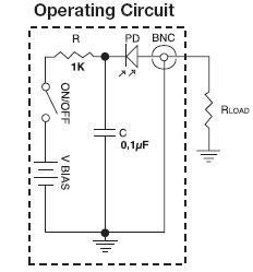
With some discussion with Dr. Noe, I now understand how the 1-photodiode circuit works to stabilize laser intensity. With one photodiode, the circuit attempts to park the laser mode somewhere and maintain a stable intensity. This also serves to keep frequency steady.
The photodiode has a polarizer in front of it. The amount of light hitting the photodiode affects the voltage across the gate in the MOSFET in the cirucit. This affects the heating level. Imagine a graph of the gain curve with a mode locked on the left side of the curve and frequency increasing as one moves right. A slight increase in cavity length increases the output wavelength slightly since laser modes only resonate with an integer number of half-wavelengths inside the cavity. This increase in wavelength means a decrease in frequency; the laser mode moves towards the left of the curve and light output decreases. The photodiode receives less light and so the voltage across the gate on the MOSFET is reduced. A reduced voltage means less current flowing through the heater. The heater heats less and so the laser tube cools slightly and slightly shrinks in cavity length. This results in a decrease in wavelength or an increase in frequency, moving the laser mode towards the right of the gain curve back to the stabilization point. The opposite happens if the tube were to expand slightly.
Feedback appeared simple to me and in principle it is. If the monitored property were to change, the system adjusts so that the property returns to the normal point. It is the combination of feedback with electrical circuits that makes it difficult to process. Some of the components in the more complex circuits are black boxes to me, although I am getting better. Some resistors and capacitors just seem randomly placed because I do not know their purpose.
This simple circuit does not produce the most stable output. This may be because of my setup, which has exposed wire connections and involves many alligator clips. But it may also be down the simplicity of the circuit which may not be able to accurately control the cavity length. When I measured the tube output, I found the photodetector/multimeter showing a signal, say .077 mA, with a fluctuation of +/- .005 mA. However, the output would suddenly jump, say down or up .020 mA, and begin to fluctuate around a new point before jumping again. It is stabilized; the unstabilized laser's output when measured with a photodetector with a polarizer in front of it oscillates in power in a sinusoidal fashion as the laser modes march across the gain curve.
31 July 2008: Stablized He-Ne Laser
Laser stablization is to be the project topic from here on. Yesterday and today, Sam "Laser Sam" Goldwasser from Philadelphia visited the LTC, sharing with his knowledge of lasers and electronics. Laser stablization was originally a project undertaken by Matt Whitrock and also by Stephanie Golmon. I had already seen the stabilized laser built in the lab and Sam also demonstrated his own stabilized laser. With appropriate stabilization, lasers can measure distances into the nanometer range.
Sam showed circuit diagrams for stablization setups starting from the most basic to the sophisticated. There are components within the circuitry that seem like black boxes to me, such as MOSFETs and opamps. In addition, it's difficult to connect the equivalent schematic drawings with what Sam actually built. It will take some reading to fully understand the principles of operation.
25 July 2008: Laser Tweezer
I helped Hamsa rebuild her laser tweezer setup today. I got a bit of experience working with a more complex setup. The setup appears simple yet can be complicated to work with at the same time. To get the best results, every piece has to be aligned and centered. Particularly difficult was getting the laser beam to travel up through the microscope by reflecting off a mirror that is not physically connected to the microscope. The correct procedure (also on Hamsa's journal):
- Put flat mirror on microscope stage and rotate objectives so that no objective is in the way.
- Align mirror so that it reflects difrectly back into the laser (only temporary of course).
- Tilt mirror to 45 degrees so the laser light goes through the microscope
- Move microscope until the beam reflection from the mirror on the microscope stage reflects directly centered on the bottom of the microscope
I have to look at good ideas for a main project. Two possible directions to go in are pulsed lasers and mode cleaner cavities.
21 July 2008: Report
I have written a great deal about photodetectors and oscilloscopes here.
16 July 2008: Findings
 Thorlabs current circuit diagram Source
After today, I found out a lot about the inner workings of the photodetector. It always perplexed me that with the photodetector turned off, the oscilloscope would still give me a reading. Today, I made an interesting observation. With the resistance set to 1 M-Ohm on the oscilloscope, I obtained a varying signal that Dr. Cohen helped to explain.
It turns out that with the photodetector off and the oscilloscope set to 1 M-Ohm, the oscilloscope was picking up the slight change in luminence of the ceiling lights, which should be varying at 60 Hz. What was confusing to me before was that even with the switch off (open), a signal could still be read. Looking at the diagram (Thorlabs: High Speed Photodetectors: Source), if the switch is open, it seems that there is no way for current to travel; there is a capacitor in the way.
Dr. Cohen was able to come up with a theory why through careful observation. With a hand covering the photodetector, the oscilloscope, which was set on Line Trigger, would show a reading at the zero line. When one uncovered the detector, exposing it to the ceiling lights, the oscilloscope reading, which is slightly oscillating due to the ceiling lights running on AC, would shoot up before coming down to the zero line. If one covered the detector, the reading would shoot down below the zero line before returning back to the zero line. Now that this was occuring with the switch open was very strange. Dr. Cohen explained to me that because the reading was returning to zero and that the reading would go below the zero line, he suspected the capacitor as seen in the circuit diagram was undergoing charge and discharge and the negative values seen in the oscilloscope may represent the current moving the other way. That the oscilloscope reading would return to zero after a change in the situation indicated support for this theory.
14 July 2008: Working with the Oscilloscope
The oscilloscope is an important tool that will be used to measure response time of the photodetector as resistance varies. It is expected that response time will rise as the resistance connected to photodetector circuit increases. This is because the cable from the detector to the oscilloscope acts as a small capacitor. [Resistance]x[Capacitance] produces the RC time constant that indicates the time delay in charging the cable that creates a delay for a signal to reach the oscilloscope. I learned a lot about the myriad dials and switches on the oscilloscope today so I should be able to evaluate the photodetector.
I need however, an array of LEDs connected to an oscillator. I found the rise time of the strobe light to be 5 microseconds--too slow. LEDs connected to an oscillator are much more responsive, but a single LED is rather dim compared to the ambient lighting. Therefore I will create an array of LEDs in parallel for a brighter light source.
10 July 2008: Photodetectors
I am back from a few days of visting colleges. It would be really useful to understand how the Thorlabs DET110 photodetector works. There are conflicting circuit diagrams. I don't understand the purpose of the capacitor in the photodetector. I will try to understand the circuit system and then test changes in accuracy and response time as I change the external resistor and voltage biasing.
2 July 2008: Mini-project Update
Work on measuring the width of the laser beam has been slow but steady. I still have yet to reach the point where I can take the photodetector and measure across the width of the beam. On Monday and Tuesday, I finished putting in the components and lined up the laser beam using two mirrors following the procedure outlined in Daniel and Simone's project, Walking the Beam. I feel the work is slow because I am still gaining familiarity for the location of things in the lab and working with optics. Simple things like finding the right posts and post holders and screwing them into the table take longer than anticipated time.
By Tuesday afternoon, everything was complete. We added an amplifier into the photodetector circuit because the voltage produced by the weak light passing through the tiny pinhole was insufficient. Then disaster struck. For some odd reason, the open-cavity laser ceased to lase and no beam was to be found. Fortunately, Marty was able to adjust the mirror at the end of the open cavity laser and fix the beam, but we lost the HG01 mode that was so perfect. I've been trying to get the beam back ever since, but it is no go. Dr. Noe theorizes that it may be because the Brewster window for the open-cavity laser is now too clean; dust on the window before helped select out other modes so that a pure HG mode would be output.
30 June 2008: Web Update
With some work, I created HTML templates for the biograph and journal pages. These can be used for future students. I modernized the code and employed XHTML transitional document type definitions. This is because the coding that defines the widths of tables is considered by the newer standards to belong to style, not content. I don't feel it's so important to glue so closely to the standards if it involves so much involvement to make valid code. Transitional allows use of older code in the HTML file while still being valid. As long as it displays properly in the most browsers properly, it's good.
Most importantly, the template files now refer to an external stylesheet instead of having the stylesheet within the header of every page. This creates a single place where the appearance of the site can be adjusted. So in sum, I created simple, but valid templates for future use.
27 June 2008: Mini-project
Before embarking on a complex project, you need to familiarize yourself with working with optics, finding materials, and setting up experiments. So you do a mini-project to achieve these goals. Hamsa has a bunch of excellent project ideas in her 25 June 08 journal entry which we discussed. My project will investigate the Rayleigh Range of non-TEM00 mode (basic laser beam) lasers.
I will use a photodetector to test the intensity of a beam across its cross-section. The photodetector will have a pinhole in front of it so that it can measure only one fraction of the beam at a time. I can measure where the laser beam begins to fall off to determine its width and I will do that for multiple points along the beam. There is more discussion about this project at my mini-project page.
Getting started on this project felt like it took more effort than expected. I needed to find posts and mirrors of appropriate size, screw them together, and position them on the table. Because of this, I will have more work to do on Monday. Monday is also when the Simons fellows arrive.
25 June 2008: Indian Lunch
Today I met Hamsa and Dr. Noe took me, Will, and Hamsa to Raja for lunch. I have never been to a solely Indian restaurant before and the food was delicious, especially the chicken. After lunch, we stayed outside to burn paper with magnifying glasses. There is certainly more science that then meets the eye burning holes in paper. How does the size of the focal spot change with different focal lengths? How would one create the strongest heat to burn the paper?
I also met Hamsa today, who is very invovled with the LTC and worked here last year. Hamsa is brilliant, very knowledgeable with a lightning fast mind; the amount she knows tells me I have a lot of studying to do.
20 June 2008
The lab needs some organizing; so much has been collected over the years. Today I sorted some of the magazines and cleaned up the shelf area. There's a lot of literature and not enough shelf space. Interesingly, the Physics Department has a beer keg on Fridays. It was pretty relaxed. With one keg at some 15 gallons, it was enough for everybody and then some.
19 June 2008: Hello, First Day
Today is my first day at the Laser Teaching Center. Dr. Noe took a picture of me wearing those glasses and set up a computer account and webpage for me. Because I have experience with CSS and HTML, I can help create a template for biography, journal, and other webpages for others who come to the LTC that way site creation is easier and more uniform. I am still not sure what sort of optics topic I will investigate but diffraction and zone plates are things I will take a good look at.
|
|
Home Laser Teaching Center |