Photodetector Behavior
Victor Zhao
Stony Brook Laser Teaching Center
July 2008
Advisors: Dr. Martin Cohen and Dr. John Noe
Motivation
This project served to increase understanding and expand knowledge about photodetectors, in particular the Thorlabs DET110 high speed photodetector. Reverse bias and circuit design were explored.Principles of Operation

Image courtesy of Wikipedia
A photodetector consists of a photodiode and accompanying circuitry that produces a current in response to light. The photodiode is a special type of diode that usually consists of a PIN junction. To normal silicon, a small amount of impurity is added; this process is called doping. A PIN diode has P-doped, N-doped, and Intrinsic (normal) silicon semiconductor. The P-type semiconductor has some 3-valence electron metal added to it while the N-type semiconductor has 5-valence electron metal added to it; this affects the lattice structure of silicon. 3-valence metals tend to attract silicon valance electrons to fill a space in the lattic structure. The result is a positively charged hole. 5-valence metals disrupt the lattice structure of 4 electonrs per atom in silicon and the result is extra electrons. Note that the net charge remains 0 for both P-type and N-type semiconductors. In the middle area, the holes from P-type and electrons from N-type recombine and a zone of depletion where current is relatively immobile is created because the charge carriers have recombined here. This is an electrically neutral and relatively nonconductive zone in the diode. The two sides where the holes and electrons came from however, are left with a difference in potential.
When incoming photons strike the photodiode in the zone of depletion, hole-electron pairs are split and each return to their corresponding sides, driven by the field created by the potential difference. An electron moving one way and a positive hole moving the other represents a flow of current.
The DET110 in the lab operates in reverse bias. To reverse bias a photodiode, the positive terminal of a voltage source such as a battery is connected to the n-type side of the photodiode and the negative terminal is connected to the p-type side of the photodiode. This serves to pull the charge carriers away from the depletion zone, increasing its width. For the purposes of photodetector operation, this decreases capacitance which increases response times.
In these investigations, the capabilities and abilities of the Thorlabs DET110 high-speed photodetector were explored in conjunction with a Tektronix 485 analog oscilloscope.
Thorlabs DET110 Images


Operation
Photons striking the photodiode are responsible for creating a current in the photodetector. The current can be directly measured by a multimeter. Alternatively, adding a load resistor into the circuit measuring voltage across the resistor is another way of recording light intensity. This has an advantage particularly for small currents from the photodetector as a result of a weak light source.
V = I * R (1)
Using a resistor load is advantageous, as shown by Ohm's Law, because a small current can be multiplied by the load resistor, producing a higher voltage which can be easily measured by an oscilloscope or a multimeter.
There is however, a hidden disadvantage to this method if fast response time is desired. Any cable has a capacitance spread throughout its length which must be charged before a proper signal can be transmitted. Typically, a 50 ohm coaxial cable will have an impedence of 30 pf/foot (source).
V = V0(1 - e^(-t /RC)) (2)
(2) is the formula for voltage across a capacitor over time where at t=0, charge across the capacitor is 0 and V0 is the voltage of the charging source. This formula is designed for simple circuits containing resistors and capacitors but what is important to extract from this formula is RC, the time constant, which influences charging speed. If resistance increases, it will take more time for a capacitor to charge. Applying this to the circuit measuring light intensity, adding resistance will make the circuit slower, raising response times.
Impedence matching is recommended to produce the fastest circuit. The 50 ohm RG-58 cable is recommended to be connected to 50 ohm inputs and outputs.
Circuitry Confusion
There are three differing circuit diagrams for Thorlabs high-speed photodetectors. There is a catalog version and another was found on Thorlabs documentation. Both of these are meant for Thorlabs DET110, the photodetector used. The DET110 has been superseded by a new series of more compact photodetectors at Thorlabs. A circuit diagram for these new photodetectors was found, which contains a bit more detail.
The confusion results from minute differences between the three circuit diagrams. What seems to be missing from the leftmost diagram is an additional implied path to ground, which has been drawn in. The greatest confusion however, was that with the switch off, the circuit diagram shows that there is no path for the current to flow, yet a photodetector turned off could still produce a signal in the oscilloscope--this is discuessed further below.

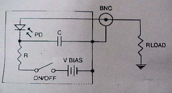
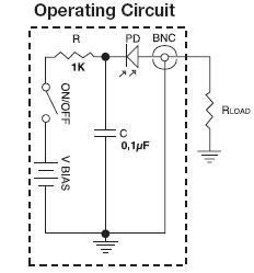
Left from right: diagram from Thorlabs catalog, diagram from Thorlabs datasheet, diagram from Thorlabs website (not for DET110)

5 mV/div; 5 ms/div
Nevertheless, an interesting observation made while working with the DET110 and the Tektronix 485 oscilloscope helped to explain the operation of the photodetector. With the photodetector off, input impedence of the oscilloscope set to 1 M-ohm, the sensitviity set to the highest setting of 5 mV per division, and triggering set to line, a sine wave graph appeared on the oscilloscope display. It was soon apparent this graph was the result of changes in brightness in the ceiling lights, which run off alternating current. The great mystery was that the photodetector was off, yet the oscilloscpe was still producing a signal. All three of the photodetector diagrams indicate that with the switch open, it is impossible for the current to flow--except through the capacitor. Dr. Cohen helped reveal the mystery.
The signal on the oscilloscope behaved strangely as the photodetector was covered and uncovered. Initially, while exposed to the light, covering the photodetector caused the signal to drop below the 0 line, indicating a negative voltage. The reading would soon return to the 0 line. When the photodetector was uncovered, the voltage signal would shoot up from the 0 line into the positive, but it would also then drop down to oscillate at the 0 line again. With the display of negative voltage and the eventual return of the graph to 0 after a change in the photodetector's situation, Dr. Cohen suspected that the capacitor was causing this phenomenon. The circuit diagrams are indeed accurate and the switch in the off position is open.
A change in the amount of light would alter the electric field and current in the photodiode. The capacitor circuit would behave as a conductor initially after a change, supporting the change in reading in the oscilloscope. After the capacitor charged however, the current, and therefore the voltage, would be reduced and in the steady state, the oscilloscope and photodetector would detect the changes in brightness in the ceiling lights.
Reverse Bias
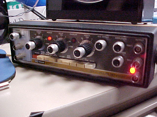
Oscillator
The photodetector's output was compared in the Off state, the On state, and a battery-less state (no voltage bias) in which a metal rod substituted the battery to serve as a conductor. An oscillator connetec to an LED produced LED pulses. The oscillator output with impedence matched at 50 ohms produced a signal rise of 5 ns. The first image in the row of images below is the signal from the oscillator directly connected to the oscilloscope with no photodetector connected.
I connected a red Radioshack LED to the oscillator. Thus there were three states: off (behavior akin to an RC circuit), on (reverse-bias operation--acurate), and battery-less (a conductor replaced the battery and the switch was closed). The LED light was rather weak, as a maximum peak of 10 mV was obtained; this is at the edge of the oscilloscope's sensitivity.
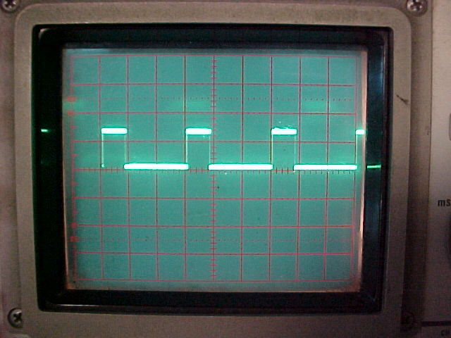

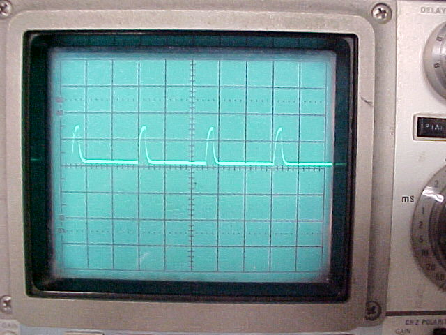
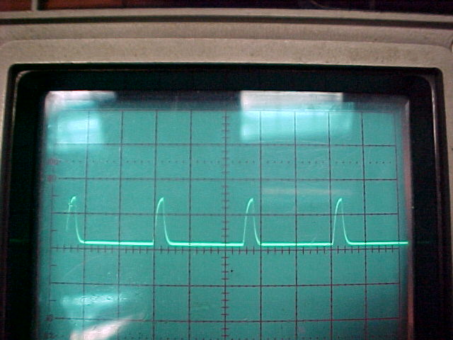
From left to right: signal profile from oscillator, photodetector off, photodetector on, photodetector on--battery replaced by conductor 5 mV/div, 2 microsecond/div
With the switch in the off position, it can be seen that the current is much weaker. Compared to the other two, the reading is not accurately reading the light level but does register the pulse. For the other two results, they are similar. The highest signal peak--achieved by angling the LED correctly into the photodetector--was only 10 mV for both.
The oscilloscope indicates for either case, the signal rise time was greatly increased through the use of an oscilloscope and LED output. This cannot be blamed on the photodetector which is rated down to the nanosecond range. It is likely that the LED was unable to make fast pulses.
While it is seen here that photodetector still operates without reverse bias. Thorlabs documentation does recommend use of the battery to create reverse bias for the fastest response times and highest accuracy and although in this case, biasing did not affect the results, there may be faster situations where recommended operation is recommended.
|
|
Home Laser Teaching Center |