
Advisors: Dr. John Noé
Introduction
Optical Tweezers are a device that can trap neutral particles using a combination of optical forces including radiation pressure, resulting from a tightly-focused laser beam. Optical Tweezers can be used to perform such delicate tasks as in-cell organelle manipulation without any consequent cellular damage. A more formal description of it is "single beam gradient force optical particle trap". To understand how Optical Tweezers works, we can consider a laser beam with certain momentum, when the direction of the laser beam changes, for example, when the beam is reflected or refracted, its momentum also changes. So we can predict that it will exert a optical force, just like a bounding ball will exert a force on the wall. This so-called radiation pressure was first discovered by James Clerk Maxwell in 1873. However, since this pressure is so tiny with ordinary light sources, it cannot be tested until a much more powerful light - laser was created. In 1986 Ashkin described the use of a single focused laser beam to trap and to manipulate small dielectric particles (Ashkin et al., 1986) for the first time. Their trapping simply consisted of using a beam of laser light to a diffraction-limited focus with a good, high power lens. Under the right conditions the intense light gradient near the focal region can achieve stable three-dimensional trapping of transparent objects. In 1987 Ashkin and co-workers showed that it can also work on living as well as inanimate material. They also showed that we can minimize optical damage to biological specimens if we use light in the near-infrared region.
Theory
Gradient Force Optical Trapping Theory
The theory of optical trapping is mainly focused on spherical particles, for the calculations is relatively simple and it's a quite good approximation in most cases. And also, as d/λ>>1, we can neglect diffraction effects and describe trapping using ray optics. The sphere is assumed to have a certain refractive index. Trapping forces are calculated considering refection and refraction of rays at the surface of the sphere.
As a tightly-focused laser beam meets a interface of a spherical particles, it will reflect and refract, and so its momentum will change. The law of conservation of momentum predicts that the photons of laser beam will transfer momentum to it, which means it will exert a force on the interface. Actually, there are two kind of forces in a opposing direction: the gradient force, which pushes the sample in the opposite direction of the incidence light propagation, or towards the focus of the laser beam; the scattering force, which pushes the sample in the direction of the incidence light propagation, or away from the light source. It's clear that the gradient force must be greater than the scattering force, so the laser beam can push the sample toward the focus, that is, to trap it.
|
Figure 1: (from [2]) The reflective and refractive rays are indicated in the graph. We can see that when a incident laser beam meet the interface, some is reflected and some is refracted. The focus of the cone of light is on the point F inside the sphere. The sphere has refractive index n1 and is immersed in a medium with refractive index n2. The momentum change from incident beam to reflective beam causes the scatting force. The momentum change from incident beam to refractive beam causes the gradient force. The angle of incidence θ1is related to the angle of refraction θ2 by the Snell's law n1sin(θ1)=n2sin(θ2). |
It's clear that good trapping requires a large cone angle. And we can see that the position of stable trapping is located somewhere below the focus: above the focus scatting and gradient forces point to the same direction. If the sphere is not at the focus, the laser beam will push it toward focus.
|
Figure 2: (from [2]) This figure shows that sphere is pushed toward the focus of the laser beam. A gradient force for downward and lateral trapping is constructed. Reflected rays and scatting forces are not drawn. We can also see that in these cases a large cone angle together with not too much power near the axis of the cone result in strong trapping forces. It can be shown that upward trapping is weakest. |
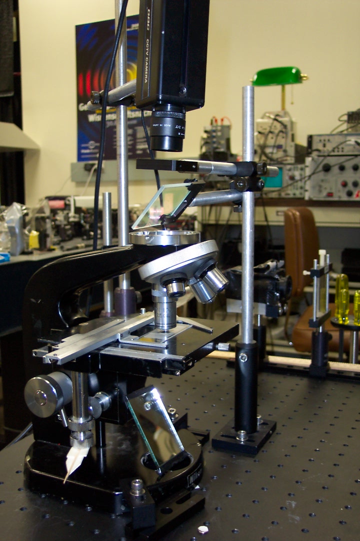
As we have seen, good trapping needs a highly convergent rays going into a tight focus. We will use a microscope to get the laser beam which meets the requirement.
The Microscope

|
Figure 3: (from [3])Light path in the microscope: F = Focal plane, O = Object (Specimen), Ob = Objective, Oc = ocular (eyepiece) |
The light path of the microscope is shown above. We put a convergent lens which has a short focus in front of the ocular (eyepiece), and it is called objective. The distance between the objective and the ocular is much larger than their focus. The object is put near the outside of objective's focus. Its real image through the objective is near the inside of ocular's focus. Then, the ocular will form a enlarged virtual image at a distance of 250 mm.
Since we hope that the laser beam are brought to a focus at a high angle so can form a good trapping, we must use an objective with a high Numerical Aperture. The Numerical Aperture is defined as the sine of half the angle of the cone of light from each point of the object, that can be accepted by the objective (α) multiplied by the index of refraction of the medium in which the object is immersed (n):
|
NA = n sin α |
The medium is usually air with a refraction index of n = 1. alpha can never be bigger than 90° and thus the numerical aperture can never outgrow 1. Its largest actual size is 0.95, since the distance between objective and the surface of the cover glass cannot reach zero. The aperture of 0.95 corresponds to an angle alpha of roughly 72°. An increase of the numerical aperture can be achieved by the choice of a medium between objective and object with an index of refraction bigger than that of air. Special oil for immersion with an index of n = 1.518 has proved to be useful. Larger indexes of refraction do not make sense, because the index of refraction of the objective itself (n = 1.525) becomes limiting. Immersion oil can be used only with specially constructed immersion objectives. If alpha has the maximum of 67.5°, the aperture is accordingly 1.515 x 0.92 = 1.40. In this experiment, we will use a microscope with oil immersion.
Description of apparatus
Diode laser
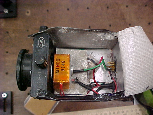
The light source used for trapping is the Sharp LT024 diode laser. It can provided up to 30 mW of near infrared laser beam with wavelength λ=780 nm. This wavelength laser beam can penetrate translucent objects and cause minimal damage to microorganisms. Although the wavelength belongs to the near infrared region, it is still visible as a deep red glow, but is more clearly viewed with an infrared viewing card.
 |
 |
|
| Diode Laser | Infrared Viewing Card | |
|
Pictures from [1] |
The laser is a box with a convergent lens. The power supply is provided by a home-made power supply. Figure 4 shows the relationship of the output power versus voltage applied.
|
Figure 4: Output power versus Voltage applied |
From the graph we can see that when the voltage is less than 3.5 V, the output power is almost 0. When the voltage increases from 3.5.V, the output power increased dramatically. At the point 5.4 V, the output power reaches 16.7 mW. After that, although the voltage keeps increasing, the output power almost remains a constant. In this experiment, the laser was operated at a standard setting of 5.4 V, which corresponds an output power of 16.7 mW.
Microscope objective
In the experiment, we use an Edmund Scientific 100x objective. The entrance aperture of the objective is about 6mm in diameter. The objective can converge parallel laser beam to a point, where the trapping occurs.
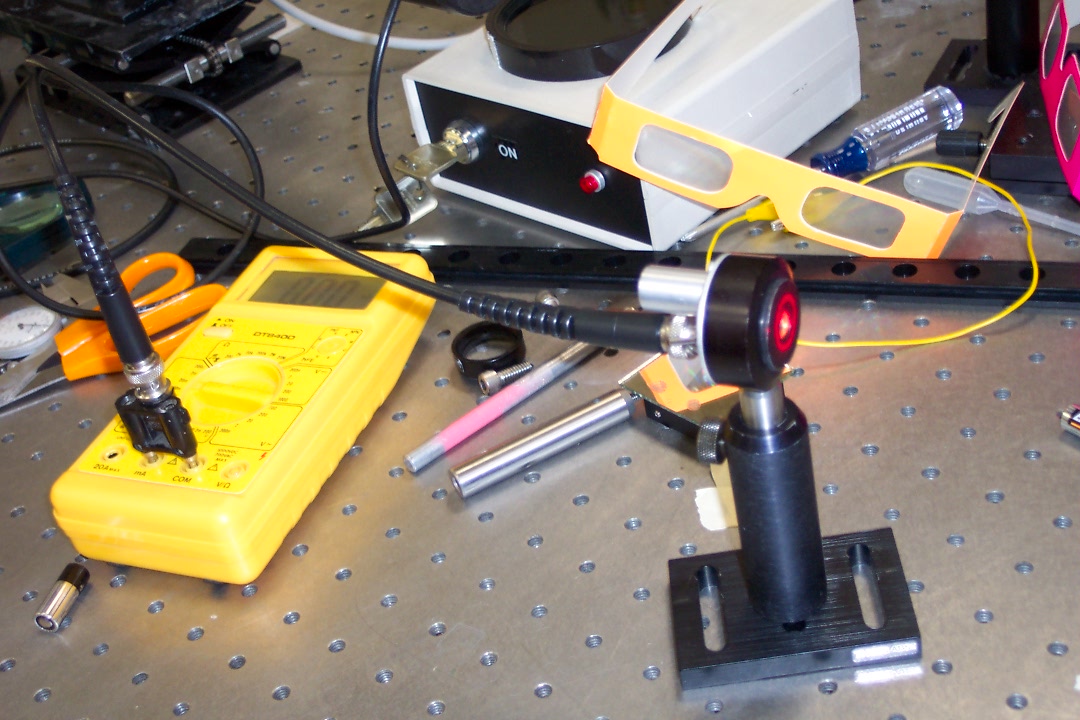
Detector
The output of the laser beam out of the fiber is observed with a photo detector (Thorlabs DET-110)
Mirrors
Mirrors are used to alter the path of laser beams.
Cylindrical lenses
Cylindrical lenses are used to from a circular beam. Their focal length are 10.0 cm and 20.6 cm respectively.
Spherical lenses
Spherical lenses are uses to expand the laser beam so that it have a correct diameter to precisely fill the objective aperture. Their focal length are 68 mm and 132 mm respectively.
Dichroic mirror
A dichroic mirror is used to bring the laser beam vertically downward into the objective aperture.
CCD camera
A GBC CCTV camera is used. An infrared filter is used to protect the camera from harmful laser beams. The camera is set vertical above the dichroic mirror and adjusted to focus at infinity.
Rose chamber
Using 1 mm thick micro slides, Parafilm, and No. 0 thickness slide covers, we can make samples in rose chamber. Firstly, Parafilm is cut with a square hole in the middle, and then laid flat on a slide. A heat gun will melt the wax to the slide surface. One drop of sample if placed in the middle of the square hole. A slide cover is finally placed onto the Parafilm, thus creating a sample with certain depth.
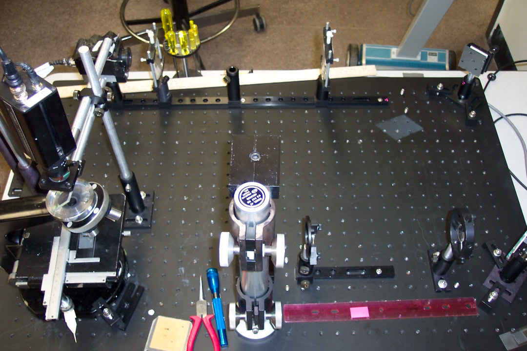
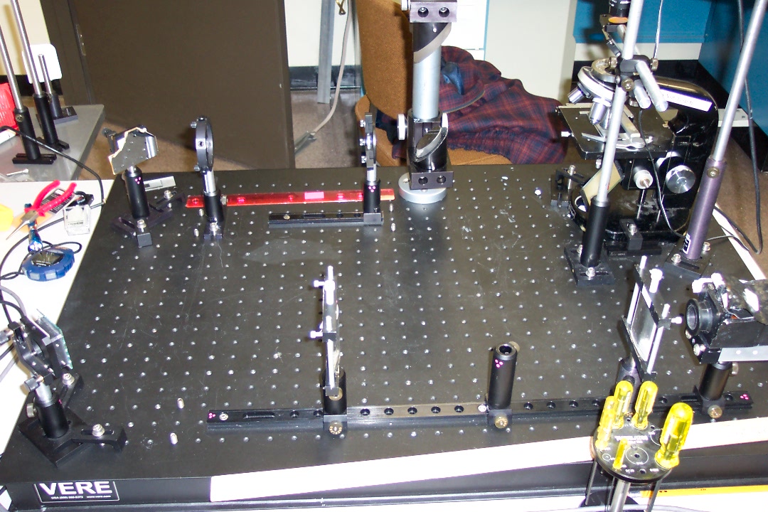
Layout
 |
 |
||
The scheme of layout of optical tweezers device is shown as follows:
 |
 |
||
|
Figure 5: Layout of optical tweezers device |
|||
As we can see from the graph, the laser beam comes out of the diode laser. The laser beam emanating from the laser diode is collimated by a collimating lens with a focal length of about 3 mm. The profile of the beam is of elliptical shape. Two cylindrical lenses are placed to make the profile circular with their distance equals to the sum of their focal lengths. The lenses are chosen such that the ratio of their focal lengths is approximately equals to the eccentricity of the ellipse. They are placed with their axes parallel to the small axis of the ellipse and are placed such that the laser beam traverses the lens with the larger focal length first. In this way, the beam is transformed such that the long axis of the ellipse becomes approximately equal to the small axis, that is, it is circularized. In our setup, the lenses have focal lengths of 206 mm and 100 mm, the ratio being 2.06. The outgoing laser beam has a profile that is approximately circular with a diameter of about 3 mm.
In order to fill the aperture of the objective, the laser beam should have a diameter of about 6 mm. So we need to expand the diameter of the laser beam. That's why we use another two spherical lenses. These two lenses are also placed a distance apart that is the sum of their focal lengths, so the laser beam remains parallel after passing through the two lenses. The focal lengths of the two lenses are 68 mm and 132 mm respectively. Since the laser beam traverses the lens with shorter focal length first, we can predict that the diameter of laser beam will expand. The ratio should be the ratio of the focal lengths, that is about 1.94. So the diameter will be about 6 mm, which is required to fill the aperture of the objective.
Trapping optimization
In order to get the strongest trapping, it's necessary to carefully optimize the diameter of the circular laser beam as it enters the aperture of the microscope objective. The key idea is that there is a direct relationship between how far the laser beam is from the axis before it enters the objective aperture and how steeply inclined the same ray is after the aperture. Those rays entering the objective on axis aren't deflected at all, while rays entering at the edge of the back aperture are deflected the most and cause the largest momentum transfer to the trapped particles. So it's natural if we can alter the beam profile so that most of the energy is distributed at the edge of the laser beam.
It happened that we got a special lens which can alter the beam profile so that energy is redistributed at the edge of the laser beam. We made a mounting for it and did some measurement.
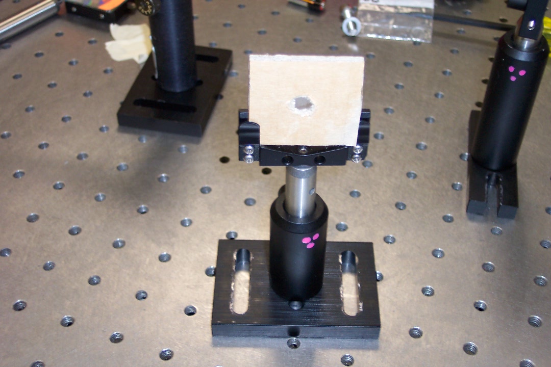 |
 |
 |
|||
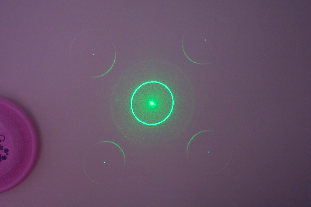
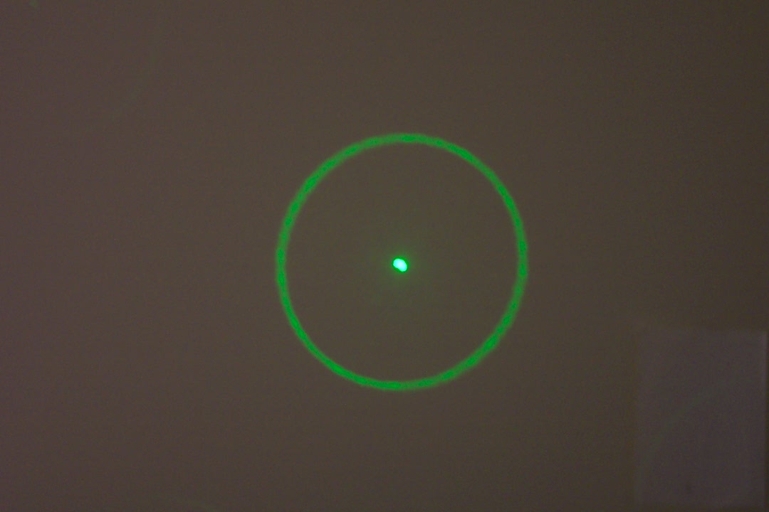
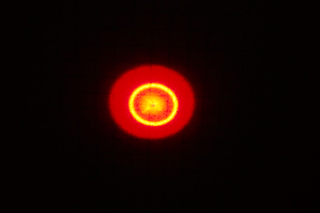
As we can see from the photos, when laser beam pass through the lens, the beam profile is changed, and a ring around the center is created.
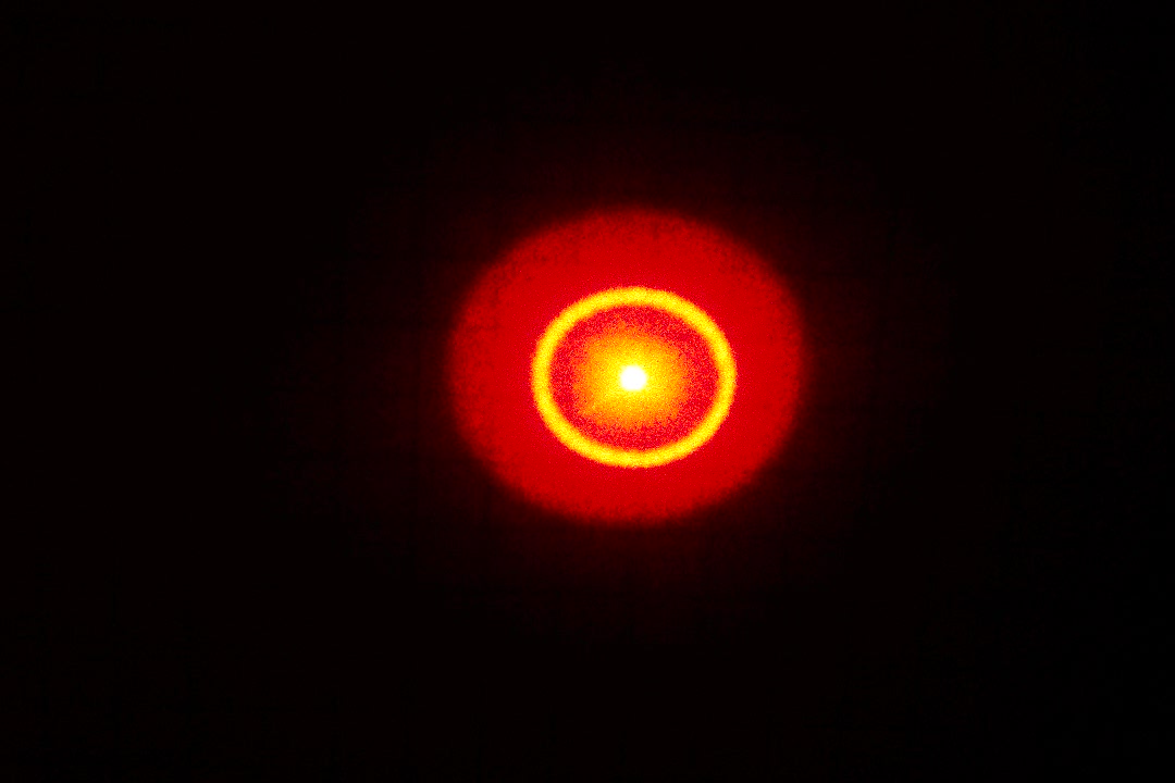 |
 |
|
The energy redistribution is measured using a He-Ne laser with wave length at 632.8 nm. The total energy of the laser beam was measured first, and then the center of the beam was blocked, so the energy of the ring can be measured.
| Energy | |||
| Center | 65.8% | ||
| Ring | 34.2% | ||
| Total | 100% |
We can see that 34.2% of the total energy is redistributed in the ring around the center.
Also, the total energy before and after the lens is measured, we can see most of laser beams passes the lens.
| Energy | |||
| Before the lens | 100.0% | ||
| After the lens | 97.6% |
Beam power measurements
| Position | Power(mW) | Power as a fraction of the power at the previous position | Power as a fraction of the original power | ||
| After laser |
16.7 |
- |
100.0% |
||
| After lens 1 |
14.1 |
84.1% |
84.1% |
||
| After lens 2 |
13.5 |
96.3% |
81.1% |
||
| After mirror 1 |
12.0 |
88.4% |
71.7% |
||
| After mirror 2 |
11.0 |
91.9% |
65.9% |
||
| After lens 3 |
8.9 |
81.1% |
53.4% |
||
| After lens 4 |
8.5 |
95.2% |
50.9% |
||
| Before dichroic mirror |
7.7 |
90.9% |
46.3% |
||
| After dichroic mirror |
6.1 |
79.3% |
36.7% |
We can see from the form above that, due to reflections, the power of the laser beam decreases each time after it pass through optical element. Only a small portion(36.7%) of laser beam reaches the aperture of the objective. In the measurement, a lens is used to make the laser beam nearly focused in the detector.
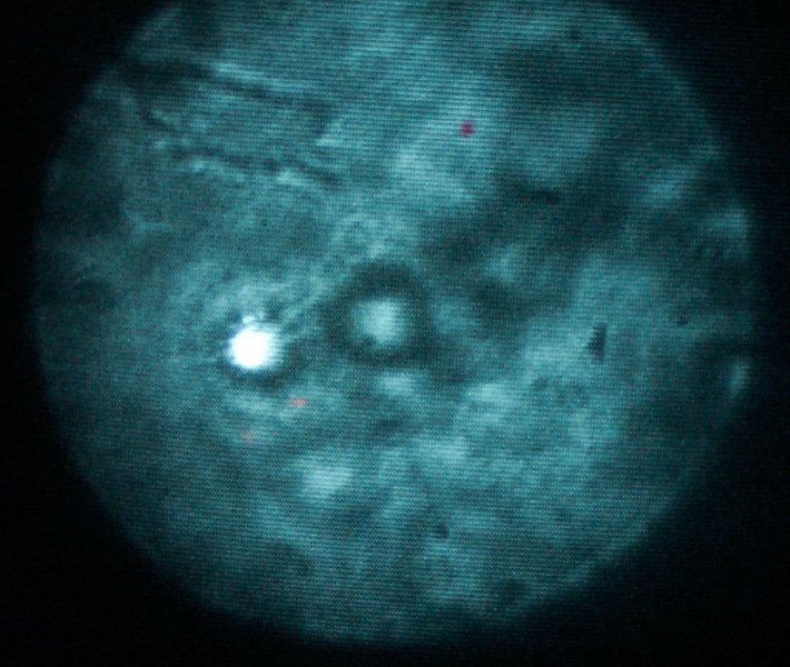
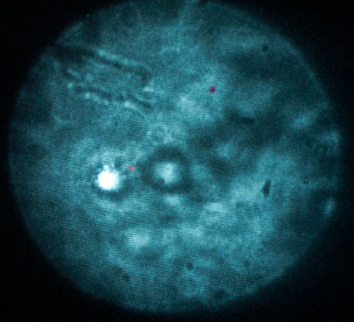
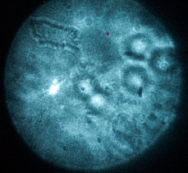
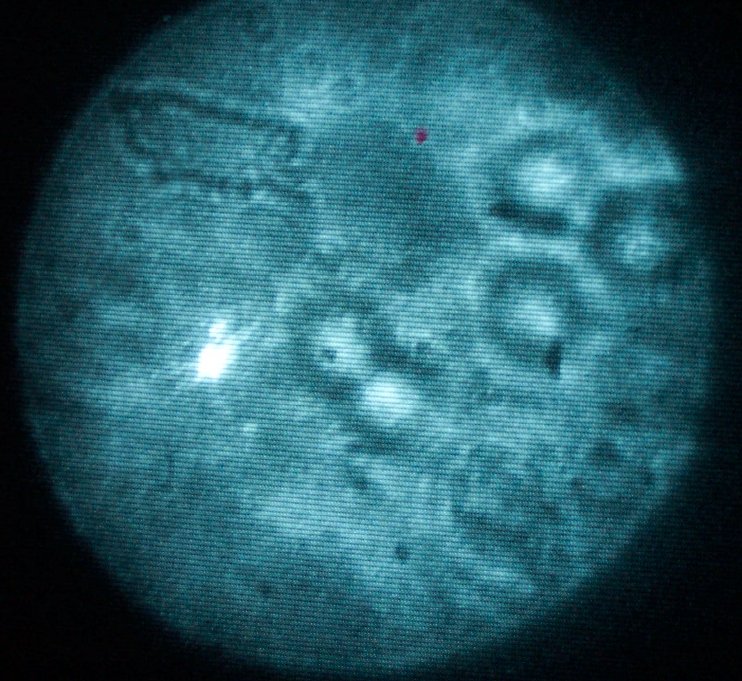
Trapping images
 |
 |
 |
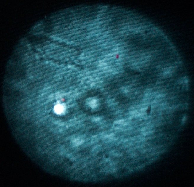 |
| Unfocused | Focused | Unfocused | Focused |
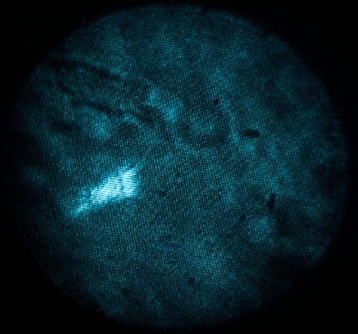
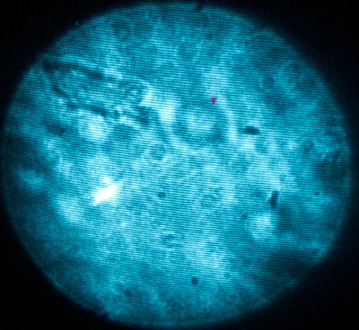
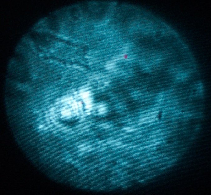
Trapping on a yeast cell:
 |
 |
 |
 |
Acknowledgements
The work is done in the Laser Teaching Center and I am very appreciated for Dr. John Noé's instruction and generous help in the experiment. I also want to thank Waldo Szczupak who cooperated with me for his much help.
References
[1] http://laser.physics.sunysb.edu/~peter/