Introduction
The purpose of my project is to study the properties of Numerical Aperture (NA) of the single-mode step-index fiber. The basic requirement for single mode fiber is that the core be small enough to restrict transmission to a single mode. Single mode fiber is optical fiber that is designed for the transmission of a single mode of light as a carrier and is used for long-distance signal transmission.
The number of the modes allowed in a given fiber is determined by a relationship between the wavelength of the light passing through the fiber, the core diameter of the fiber, and the material of the fiber. This relationship is known as the Normalized Frequency Parameter, or V number. The mathematical description of the V number is V= 2 * (pi) * NA * a / lambda
		NA =     Numerical Aperture(see below)
		a  =     fiber radius (microns)
                lambda = wavelength (microns)
A single-mode fiber has a V number that is less than 2.405, for most optical wavelengths. It will propagate light in a single guided mode.
A multi-mode fiber has a V number that is greater than 2.405, for most optical wavelength and therefore will propagate in many paths through the fiber.
The numerical aperture (NA) is a measurement of the ability of an optical fiber to capture light. All fibers have acceptance angle. The sine of the half of the acceptance angle of a fiber is known as the NA. The NA of the fiber, and also the acceptance angle, is determined by the ratio of refractive indices of the optical fiber core and its cladding. Rays entering the a fiber at a angle greater than the NA will not be reflected internally.
Experimental Set-up
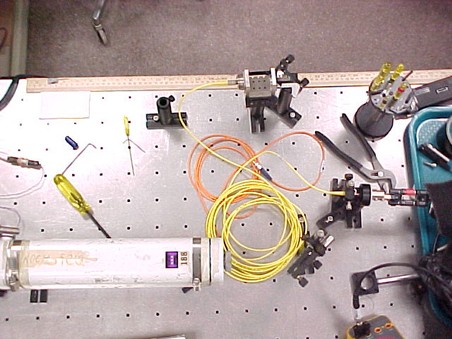

Apparatus description:
- Helium-Neon laser (Metrologic): Wavelength = 633 nm, power = 1 mw.
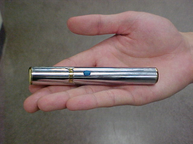
- Green laser pointer (Edmund Scientific): Wavelength = 532 nm, power = 1 mw.
- Two mirrors: mirror 1 is for x-y alignment, mirror 2 is for angular adjustment.
- Step index single-mode fiber.
* Supplier: Thorlabs * Catalog Number: P1-3224-FC-5 (arrived in March, 2001) * Operating wavelength: 630 nm * Length of the fiber: 5 m * Mode field diameter (MFD) 4.0 µm * Cladding diameter: 125 µm * NA: 0.12 * V parameter: 2.35 for 630 nm light -
Detector: The output of the laser beam out of the fiber is observed
with a photo detector (Thorlabs DET-110) together with a multimeter
and a resistor or R = 10 kohms. Sometimes a smaller detector of the
same type was used (DET-210).
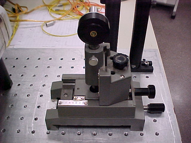
- Translation stage to move detector in small steps.

Measurement and Result
- First catch the laser beam into the fiber by adjusting the two mirrors.
I used the way that Xueqing Liu describes on
her webreport.
- Measure the NA of the fiber.

NA = sin (theta = half-cone angle)
We measure the width of the laser beam by measuring the Gauss profile of the beam coming out of the fiber.

I fit the data to the formula y = y0 + A * exp { -2 (x-x0)2/w2 } using the program Origin 5.0.
I get y0 = 50.9 mV, which is an offset due to the intensity of the light in the room; x0 = 41.2 mm, which is the center of the Gaussian profile; and width w = 26.4 mm. This means that a point 26.4 mm from the center of laser beam is the 1/e2 = 0.135 intensity point.
I regard w = 26.4 mm as the radius of the spot size, and the distance between the end of the fiber and the front of the detector is L = 295 mm. So I get
NA (1/e2) = sin(theta) = 0.089This value is smaller than expected value, which should be 0.12. Why?But on the page 238 of the THORLABS catolog book, there is a sentence that says that NA for a similar type of fiber is measured at 1% power angle in the far field. At the 1% power angle, I get the radius of the laser beam is 40.1 mm. And the distance between end of the fiber and laser beam is 295 mm. So we get
NA (1%) = sin(theta) = 0.135This value is greater than expected value, which should be 0.12. Why?This may be caused by the detector. The detector is not a spot but a square with certain area, so it will expand the Gaussian profile outside. To prove this, we remeasure the profile by a detector with smaller area. The figure following is the Gaussian profile of laser beam which is measured with a small detector.

In the same way as before we get L = 293 mm, w [1/e2] = 25.7 mm, w [1%] = 40.0 mm, and therefore
NA (1%) = sin(theta) = 0.131This value is a little less than 0.135 as expected, but it is still greater than 0.12. - NA of a fiber is related to a certain wavelength. When I let green
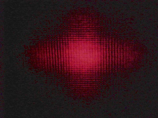
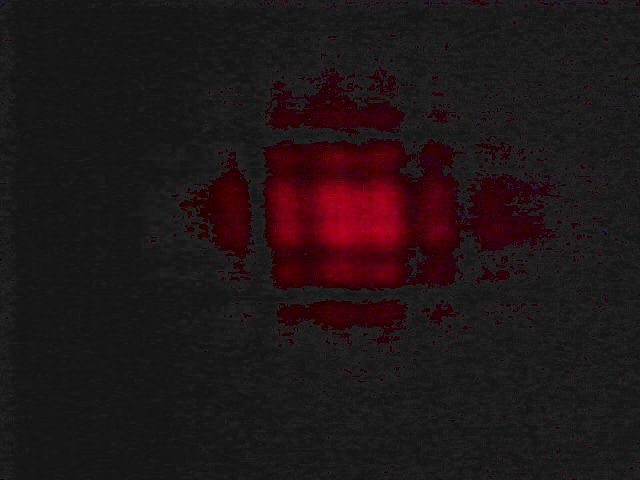
laser beam (wavelength is 532 nm) pass through the fiber, the laser
beam coming out the fiber is no longer single-mode.

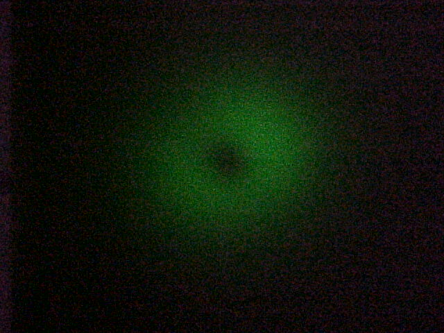
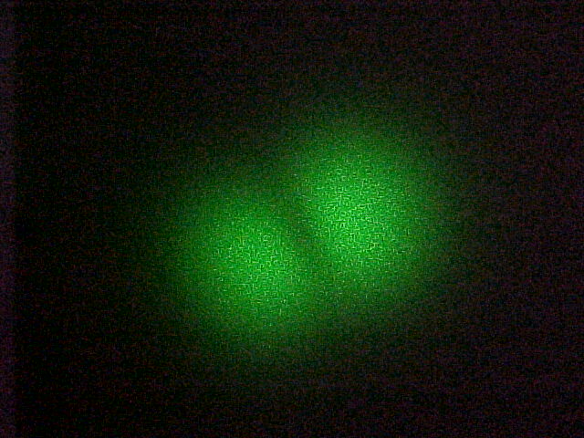
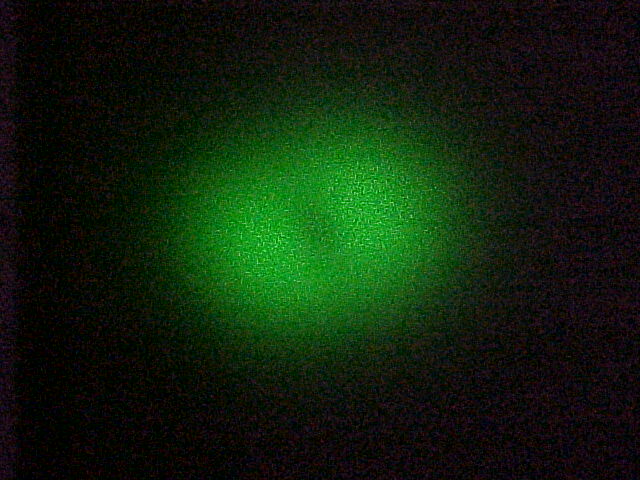
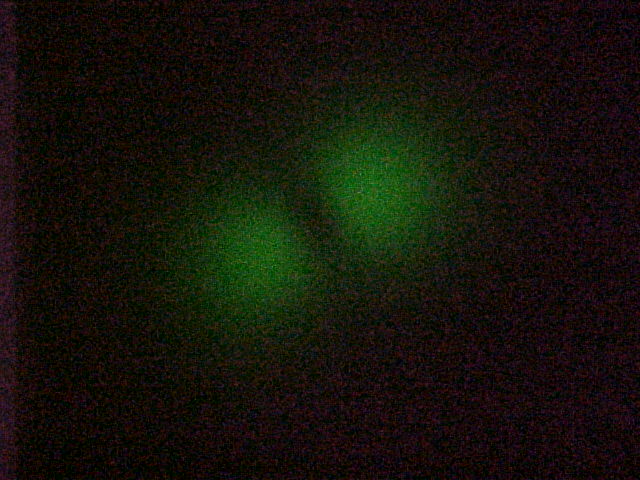
By adjusting the angle of two mirrors we get different modes of the laser beam, as shown in the above pictures. The reason is that the wavelength of the green beam is so small that fiber can not restrict transmission to a single mode.
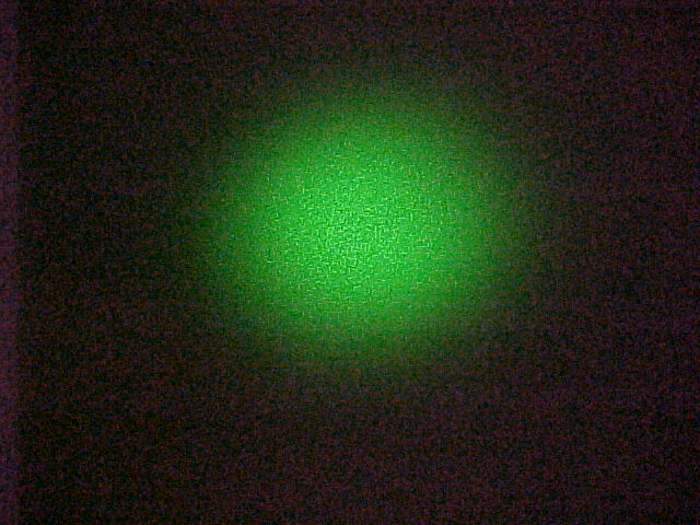
As to the last picture, it seems still to be a Gaussian profile. The figure below is the result of the measurement.
Using the 1% beam radius (measured with the larger detector) in the same way as before we get NA (1%) = sin(theta) = 0.147This number is about 9% bigger than the NA = 0.135 measured with the red light.
The Normalized Frequency Parameter (V number) is V = 2 * 3.14 * NA * a / wavelength = 2.80 if I use the specified NA value NA = 0.12 and it is V = 3.38 if I use my measured NA = 0.147. Either value is greater than 2.405, which explains why the fiber is multi-mode.
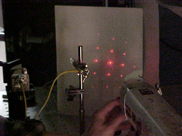
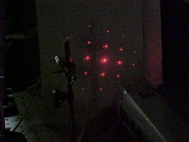
Another Interesting Thing (Discovered by Doug Broege)
If we put a " rainbow glasses" very near at the end of fiber. We can see an interesting phenomenon as shown above. And there is no such a phenomenon if the laser beam dose not pass through the fiber. This maybe because???
Acknowledgements
I am very appreciated for Dr. John Noé's instruction and generous help in the experiment. I would like to thank Prof. Harold Metcalf for his much help. Many thanks to Doug Broege, Xueqing Liu and Xiyue Miao for helping me make the experimental set-ups.
Back To Home