Learning How Laser Beams Propagate
Deb Klein
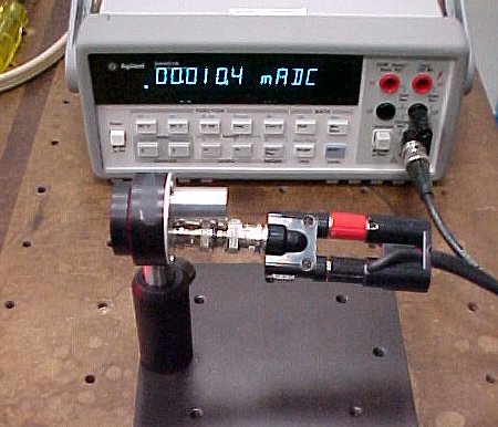
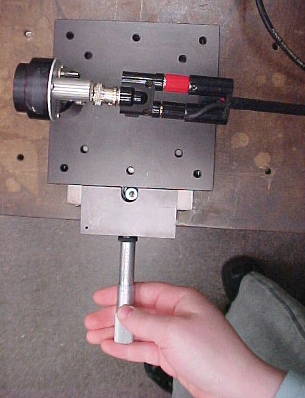
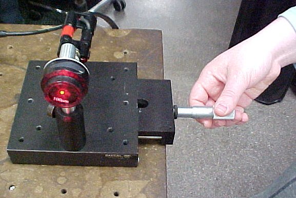
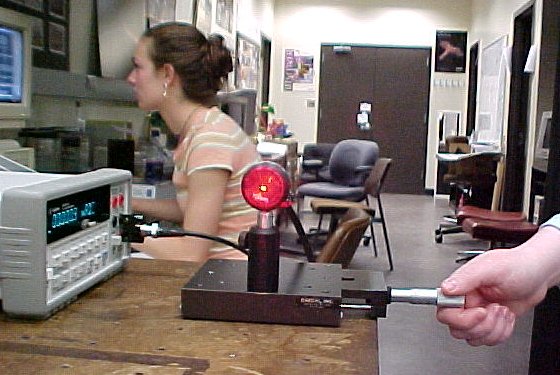
How I Found My Project ... (or it found me)February was a frustrating month spent racking my brain for some possible interest of mine that might translate into a project. March was not shaping up to be any more fruitful, but they (the ever present "they") say that as soon as you give up, you find something. They are wrong. I had not given up yet when I read a news story about some guy who got arrested for the laser/pilot incident. It was reported that the laser used to "temporarily blind" the pilot was a simple hand-held green laser pointer. Now at this point I had not yet learned much about lasers but it didn't seem as though a little hand-held laser could blind a pilot flying a plane at 3000 feet or higher. I figured a good plan for a project would be to calculate how bright the laser would be at that distance. I ran this by Dr. Noé and to my dismay, he insisted that I continue searching for other topics of interest. Utterly crushed and convinced I would never find anything I really was interested in I moped for a few more weeks. As luck should have it I have as my home page on my web browser this awesome, amazing web site: Refdesk.com: Reference, Facts, News. When I had the time I would browse their "Site of The Day" link. One lucky day, the site listed was How Blu-Ray Discs Work. I spent an hour reading up on these discs, and decided this was my passion. I am very interested in computers, and this new data storage device was fascinating to me. Even with my new-found passion, my project did not really take off until, coincidentally, Dr. Noé discovered an article in the March issue of OPN (Optics and Photonics News) about new technology for data storage, including information about Blu-Ray Discs. He suggested that I could find out what the smallest spot a laser beam can be focussed to, which directly affects the amount of data it can store on a disc. He also made a comment -- which at the time was rather cryptic -- about some connection between how quickly a laser beam spreads out, and how small it can be focused. Well, a few short weeks later I learned the truth of this statement ... For my project I started out by carefully measuring the intensity distribution of a laser beam, and comparing this to the theoretically expected shape. I learned how this single measurement can be used to determine the size of the beam at any distance away from the laser. I then related the same equations to the opposite situation, of focusing laser light to a small spot. Finally, from what I had learned about divergence I made an estimate of the brightness of the laser light that the pilot would have seen. Measuring the Intensity Distribution of a LaserExperiment Details:The intensity distribution of a typical laser beam was measured by moving a photodetector on a translational stage in increments of mils (1/1000th of an inch). The detector was mounted behind a hair-sized (100 micrometers diameter) pinhole, which was located 145 cm away from the output end of the laser. The laser used was a 10 mW Melles-Griot He-Ne laser (wavelength 632.8 nm). The light intensity is proportional to the electrical current produced by the photodetector, which was measured with a milli-ammeter.
Click on thumbnail for full-sized picture
Physics Background:The intensity of a laser beam is not uniform, rather the intensity is at a maximum in the center of the beam and drops off toward the edges. In theory, the behavior of the intensity of a cross section of the beam is that of a Gaussian distribution. This behavior is represented by the following equation: I(x) = A exp[-2 (x - x0)2/w2] Where I(x) is the intensity at a point in the cross-section of the laser beam, A is the maximum intensity at that distance away from the laser, x is the radial distance across the beam, x0 is the center of the beam (point of maximum intensity), and w is the width or radius of the beam (1/2 the diameter). We can see that if the measured distance x - x0 is equal to the width w then the intensity becomes
A exp[-2] This is how we define the end of the beam, when the intensity drops off to 1/exp[2] of the maximum intensity at that distance away from the laser.
Results:Dr. Noé helped me set up a spreadsheet to compare my measurements with the theoretically expected Gaussian form. The theoretical Gaussian distribution has three constants: A-maximum intensity, xo-middle of the beam (point of maximum intensity), and w-width or radius of the beam (1/2 the diameter). Each constant was put into a separate cell where it could easily be changed to adjust the theoretical form. For each measured point the square of the difference between theory and measurement was saved in an "error" cell, and the sum of these values was displayed to show the "goodness of fit." I was able to adjust the theoretical graph constants until my goodness of fit was a nearly perfect value of 6.45 (the lower the value the better the fit). This graph compares my measured values (blue data points) to the theoretical Gaussian graph (red line). As you can see, the fit is practically perfect. From this analysis I found that the beam radius w(z) at z = 145 cm is 0.837 mm.
Gaussian Light Intensity Distribution
Laser Beam Divergence
Physics Background:Contrary to popular assumption, a laser beam does not retain its original width over an infinite distance. Rather, it slowly spreads out, or diverges. As the beam leaves the laser it is initially parallel, but it immediately begins to spread out at a steadily increasing rate. The rate of spreading out eventually reaches a maximum value called the divergence angle θ given by the equation:
θ = (2/π)*(λ/2 w0) In this equation w0 is the radius of the beam where it leaves the laser (at distance z = 0) and λ is the wavelength of the laser. The inverse relationship between the divergence angle θ and the minimum or initial size of the beam w0 means that the smaller the initial size of the beam is, the faster the beam will spread out as it travels away from the laser. The expanding laser beam can be described by a hyperbola, as summarized in this equation
w(z) = w0[1+(z/z0)2]1/2 Here w(z) is the radius of the beam at a distance z away from the laser, w0 is the minimum beam radius, and z0 is the "Rayleigh range" given by z0 = [π/λ] * w02
Beam Waist and Raleigh Range
These concepts and relationships are summarized in the diagram shown above. It can be seen that the Raleigh range z0 is the distance over which the beam radius increases by a factor of √2 = 1.414 ... over its initial minimum value w0. Twice the Raleigh range or 2 z0 is called the "depth of focus" because this is the total distance over which the beam remains relatively parallel, or "in focus." The hyperbolic shape of the beam in the region near z = 0 is often referred to as the "beam waist." Variations on this are that the beam "makes or forms a waist" at z = 0. Thus w0 is called the "beam waist radius" and 2 w0 is the "beam waist diameter" or "spot size." Graphing Laser DivergenceMy intensity graph told me the radius of the beam w(z) at z = 145 cm. To use this information to determine the beam radius at other distances we set up a spreadsheet to create a plot of the hyperbolic divergence equation (red line). The shape of the "swoop curve" in the plot could be adjusted by changing the value of the waist radius in the spreadsheet. I varied the waist radius in small steps until the swoop curve passed through my measured data point (blue squares). This procedure gave a value for the waist radius of w0 = 0.04 cm. I later found the beam waist radius at z = 0 that best matched my beam size measurement at 145 cm in a different way, directly from the formulas, and obtained a value of 0.0396 cm (pretty darned close to the graph's value!!!!!). To do this I combined the equations for w(z) and z0 to get an equation for w0 in terms of w(z) with z = 145 cm. I solved the equation using the equation solver on my TI-89 calculator.
Measured Beam Divergence
Focusing Lasers (Divergence Reversed)
Physics Background:
Focusing Laser Light
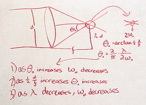
Light being focused behaves just like diverging light, only reversed, and the divergence angle equation (θ = [2/π)*(λ/2w0]) is equally valid. This sketch shows the behavior of light being focused through a lens with focal length f. Light entering perpendicular to the lens is focused to a point along its axis at a distance equal to the focal length. It can be seen from the diagram that the angle θ0 at which the laser beam of initial diameter d is focused is then given by: θ0 = arctan[1/2 d/f]
From this equation combined with the divergence angle equation we can conclude four things:
It would appear from these observations that in order to obtain the smallest possible waist w0 we want to minimize the focal length f and maximize the focusing angle θ0. However, there are two complications:
These observations have important implications for the problem of maximizing the data storage on discs, as I will explain later. :) Demonstrating Laser Beam Waists and Focal DepthsWe created a graph that displays three different beam curves, with adjustable waists. Using this, we were able to visually demonstrate the dependence of the depth of focus on the waist size, with a smaller waist creating a shorter depth of focus.
Waists and Depths of Focus
Click on thumbnails to enlarge image
So What Did the Pilot See?
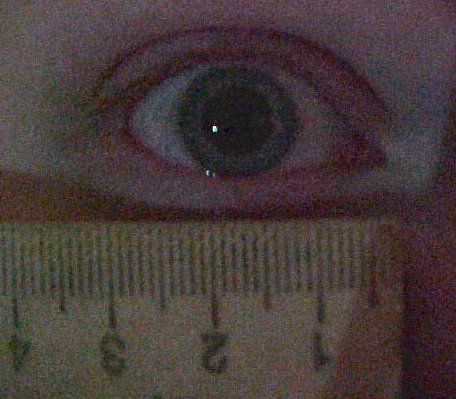
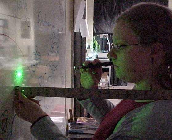
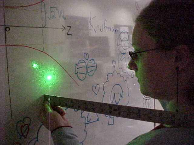
To estimate what the pilot saw we can start by assuming that the divergence of a green laser pointer (λ = 532 nm)is about the same as the measured divergence of the red HeNe laser beam (λ = 633 nm). This will be exactly true if the waist size of the green laser is slightly smaller (by a factor 532/633) than the waist size of the red laser. We can also assume that the total power of the beam is 5 mW, the maximum legal value for a laser pointer. From this we can calculate the "irradiance" (power per unit area) at a distance of 3000 feet. The exact calculation takes into account the Gaussian profile of the laser beam, in other words, that the intensity is only a maximum at the exact center of the beam. However we can make an useful approximate estimate by assuming that the 5 mW total laser power is uniformly distributed over the spot size of the beam at 3000 feet, which was calculated to be about 7000 cm2. To find the power entering the pilot's eye, we need to know the area of his/her pupil. The standard size for a dark-adapted pupil used in laser safety calculations is 7 mm diameter. The same value was found for my eye by taking a picture in a darkened room, as shown above. The power value we found was 120 nW. (check this number) When we started to think about how bright this amount of light would actually apppear Dr. Noé suggested that we imagine placing a "green light bulb" at some distance from the eye that we could calculate, that would produce the same irradiance. The next step was to realize that a perfect green light bulb is just the spot made by shining the laser pointer on a diffuse white surface! The area that the total power of the laser is distributed over is just that of a hemisphere. The light isn't distributed uniformly at all angles, but to get a rough estimate we can assume that it is. We found that an irradiance of 120 nW over a 7 mm diameter circle occurs when the radius of the hemisphere is approximately one foot. Our conclusion: what the pilot saw is about what I am seeing in the pictures above !!!! Postscript: I loved this project so much I decided to become a Physics major !!!!! 
Click on thumbnail to enlarge
References
|