Modeling Diffraction by a Circular Aperture
Illuminated by a Diverging Light Beam
William Weiss, Marty Cohen and John Noé
Laser Teaching Center
Department of Physics & Astronomy
Stony Brook University
Introduction
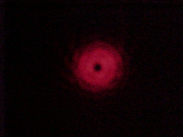
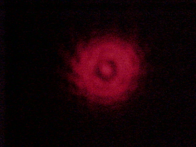
Laser Teaching Center students are encouraged to be curious, and often just asking, "I wonder what would happen if ..." can kick-start interesting research. Thus my project came about through a chance observation while examining the diverging Gaussian wavefront emerging from a single-mode optical fiber. While shining this light through a pinhole we observed an unexpected and interesting diffraction pattern with an umistakeable dark spot in its center. As the distance between the tip of the fiber and the pinhole was varied this pattern changed to others with a bright or dark center surrounded by dark rings. Only at relatively large distances did we observe the familiar Airy pattern that we initially expected.
Setup
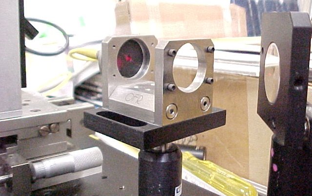
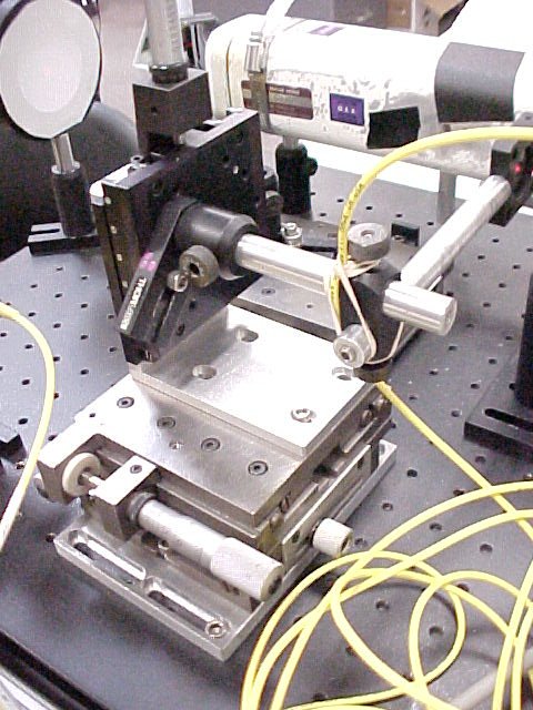
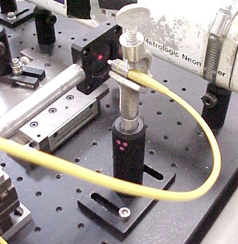
The patterns were studied systematically by mounting a 100 micron diameter pinhole on a 3-D translation stage. This setup allowed the pinhole to be accurately centered in front of the fixed fiber and the pinhole-fiber separation to be varied in steps as small as 25 microns from 0 to 20 mm. As before, the source feeding the fiber was a low-power red He-Ne laser (wavelength = 632.8 nm). The diffraction patterns were observed by eye and photgraphed on a small screen placed about 35 cm from the pinhole. The divergence of the light emerging from the fiber was measured in a separate experiment by scanning a small photodetector across its profile. The profile was found to have a Gaussian shape as expected, with a 1/e2 angular diameter of 2 x 0.08 radians. The corresponding measured beam diameter at the tip of the fiber is 4.8 microns, in good agreement with the manufacturers specification of 4.0 microns.
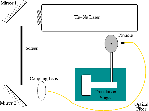
Schematic of setup. I used the 2 mirror coupling system in the lab with a lens to focus the light into the fiber optic cable. The light emerges at the other end of the fiber and is incident on the pinhole, which is attached to the translation stage.
Diverging Beam

Caption goes here ....
Fourier Optics
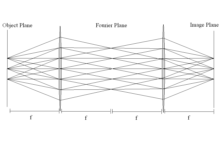
Caption goes here ....
The observed patterns can be understood by considering the Fresnel number N = a2 / λL, where a is the aperture radius, λ is the wavelength, and L is the fiber-to-pinhole or pinhole-to-screen distance. Before the pinhole N is of order unity while after it N ~ 0.01. The former value indicates that the phase of the light reaching the pinhole varies significantly with radius, while N << 1 indicates that the path length from any point on the pinhole to a given point on the screen is essentially the same (the Fraunhofer approximation). In the Fraunhofer approximation each pattern is the Fourier transform (FT) of its (complex) aperture function, T(r). The FT integrand reduces to the product of the Gaussian intensity function, the phase function, and a zero-order Bessel function. Mathematica was used to numerically evaluate the integral across the screen and plot its square, the observable intensity distribution I(r), for a number of appropriate fiber-pinhole separations. Each plot took a few minutes. The calculated distributions are in very good qualitative agreement with the sequence of observed and photographed patterns. Work is in progress to extract numerical intensity profiles from the images in order to make a more precise comparison.


