Properties of a Liquid-Drop Variable Lens
Scott Huang - Laser Teaching Center - Summer
2006
Introduction
Lenses have a long history as tools, used initially for concentrating sunlight to light fires, then used to correct vision and magnify objects. Naturally occuring lenses can often be seen in the form of liquid water droplets, which act as miniature convex lenses.
Optical elements with variable properties are extremely useful in many optical instruments, and have the potential to significantly advance modern day consumer products. Adaptive mirrors, for example, play an integral role in correcting for wavefront aberrations caused by atmospheric conditions, enabling ground-based telescopes to capture accurate images. While the actual shape of a mirror's surface can be altered to change the path or wavefront of light, varying the properties of a lens is inherently more difficult. Unlike a mirror, light passes through a lens instead of reflecting off of it, so the shape of the material must be distorted without altering its transparency and other optical properties. Conventional lens-making technology, which relies on grinding or molding solids, becomes ineffective when attempting to construct variable lenses.
On a small scale, transparent liquids offer properties similar to common lens materials, but also allow for variability in shape.
In this project I created a simple mechanically-variable liquid lens, studied its properties and used it as a simple microscope lens.
What is a Lens?
A lens is characterized as an optical element that refracts light to either converge or diverge, based on the curvature of the lens' surface and the material's index of refraction. The refracting power of a lens is governed by Snell's Law, n1sin(θ1) = n2sin(θ2), which states that the angle of refraction that a ray of light passing from one medium to another undergoes is dictated by the respective refractive indices of the two mediums. Generally speaking, a lens has a higher index of refraction than its surrounding medium (air), and light entering the lens bends towards the normal of the boundary between the lens' surface, while light exiting the lens bends away from the normal.

In a biconvex converging lens, the curvatures of each surface are reversed, so the light refracts twice in the same direction. The focal length, or the distance at which parallel light entering a converging lens focuses to a point, of a lens is dictated mainly by two properties of a lens: the material's index of refraction, and the curvature of the lens' surfaces. As the index of refraction of the material increases, the refraction angle at each surface increases as well, effectively shortening the focal length. Similarly, a larger degree of curvature, or shorter radius of curvature, results in the light entering the lens at a more oblique angle, which consequently shortens the focal length of the lens. The focal length of a lens can therefore be varied by altering either the index of refraction or the curvature of the lens.
While materials like glass and plastic are commonly used to construct traditional lenses, they are unable to adequately fulfill the requirements of a variable lens. The act of deforming a solid lens to alter its optical properties consistently and repeatedly is infeasible and stresses conventional materials. Transparent liquids, on the other hand, can be used as easily deformable lens materials. This effect can commonly be seen in nature, where observations made through water are distorted or offset due to refraction. The main difficulty in employing liquids as lens materials lies in maintaining and controlling the curvature of a liquid lens. On a small scale, however, a water droplet is greatly affected by surface tension, and forms a highly curved meniscus that acts as a convex lens surface. This combination of small scale and large curvature is extremely beneficial when addressing the purposes of a variable lens.
Since the overall focal length of entire optical systems can be manipulated by adjusting the spacing between individual lenses, there has previously been relatively little need for variable single element lenses. Now, however, the miniaturization of optical products and consumer devices such as the cameras found within mobile phones has led to a search for a small-scale deformable lens that does not require space-occupying physical displacement in order to vary focal length. Unlike conventional lens materials, the deformability of liquids offers versatility when manipulating lens properties, especially on a small scale.
Microscopy
A common utilization of converging lenses is in the field of microscopy, which employs a converging lens to create an image of the object that is larger than the object itself, known as magnification. The main function of a microscope is to allow the eye to see details that are too fine to be resolved without assistance. This is accomplished by using a lens to create a magnified image of an object. In other words, a microscope simulates the effect of physically moving the eye closer to an object, which cannot ordinarily be done because the eye lacks the ability to resolve the image at such short distances. When an object is placed slightly further than one focal length from a convex lens, a real, inverted and magnified image of the object is created on the other side of the lens.

This is the basic premise of a simple microscope, which consists of a single convex lens. Magnification is given by the ratio of the image distance, the distance between the lens and the image, and the object distance, the distance between the lens and the specimen. As the object distance decreases, the size of the magnified image increases proportionally. When the object distance reaches the focal plane of the lens, however, the rays exiting the lens emerge parallel, and no real image is created. In order to create a real image, the object distance must be greater than the focal length of the lens. A shorter focal length allows for a shorter distance between the object and the lens, and enables greater magnification.
The addition of a secondary converging lens for additional magnification, as in the eyepiece of a compound microscope, takes the real image produced by the first lens and uses it as the object. If the image is closer to the secondary lens than its focal length, a larger, virtual image is created. This occurs because the rays that originate from within the focal distance of the lens are refracted inwards but do not actually converge to a point. Instead, they emerge from the lens as divergent rays, and the eye traces the rays back to their apparent origin, forming a virtual image.
The microscope as an instrument has its roots in Anton Van Leeuwenhoek's simple microscope - a tool that employed a single spherical lens to achieve large degrees of magnification. This was possible because of the extremely small size of the spherical glass lenses Leeuwenhoek created. A spherical lens is essentially a glass ball (which acts as a biconvex lens with a radius of curvature equal to the radius of the lens itself), which has a focal length directly proportional to its radius. The ratio of the focal length to radius is determined by the index of refraction of the sphere.
The relationship between these the physical properties of a
lens and its focal length f is given by the Lensmaker's
equation:
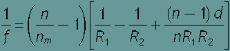
n is the refractive index of the lens material (water = 1.33)
nm is the refractive index of the surrounding medium (air = 1.0))
R1 is the radius of curvature of the lens surface closest to the light source
R2 is the radius of curvature of the lens surface farthest
from the light source
d is the thickness of the lens (the distance
along the lens axis between the two lens surfaces).
For a spherical lens, R1 and R2 are equal in magnitude but have opposite signs (for the first surface, convex is positive, and for the second
surface concave is
positive), and d is equal to 2R. This allows the Lensmaker's equation to be simplified to
(f/r) = (1/2) (n/(n-1))
Given this, a spherical water droplet (n=1.33) would have a focal length of 4.33R/2 .A variable liquid lens with dimensions that are varied based on the diameter of the drop, however, constantly changes shape, and with surfaces less curved than that of a sphere, has a longer focal length. The focal length for a given sphere of water represents the minimum focal length of a liquid lens at that diameter.
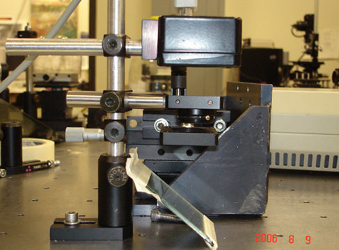
Setup
A liquid water lens was created by suspending a drop of water in the opening of a horizontally mounted adjustable diaphragm. An optical diaphragm, or iris, is ordinarily used as a stop to regulate the amount of light passing through an optical system. When a drop of water is placed in the opening of the diaphragm, the edges of the drop adhere to the edge of the diaphragm. By increasing the size of the diaphragm opening, the drop's diameter is increased, and the drop itself is stretched. The adhesion to the edge of the diaphragm forces the drop to increase in size, while cohesion keeps the drop together. Because the drop maintains a constant volume, the increase in diameter means that the thickness of the drop must decrease, and the curvature decreases accordingly. By changing the diameter of the opening, the liquid is stretched or compressed across the opening, resulting in variations in surface curvature. As the aperture increases in size, the drop flattens, reducing its surface curvature and increasing its radius of curvature and focal length.
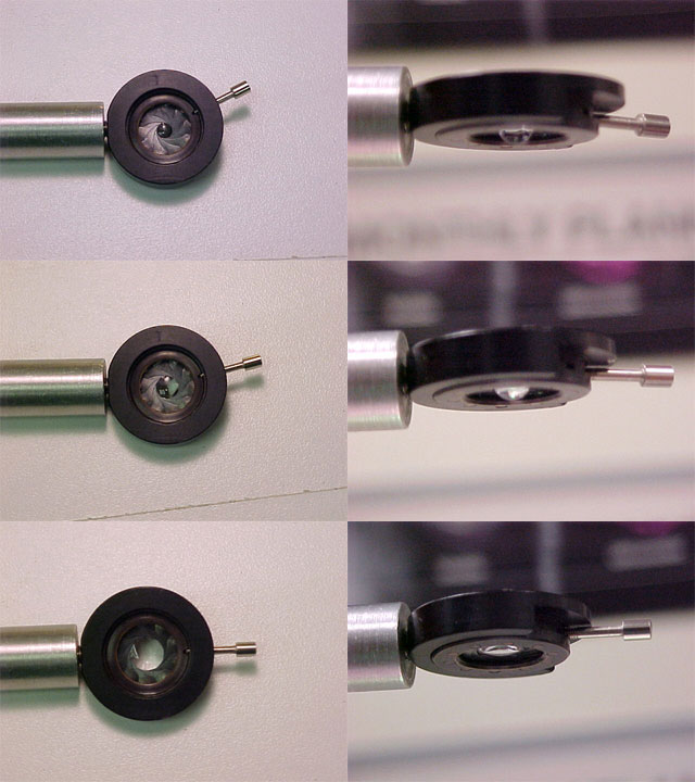

For the liquid lens, the radius of curvature on either side of the lens and the thickness of the lens are both dependent on the diameter of the drop. Due to the vertical orientation of the iris and the size of the drop, gravity has an effect on the drop's curvature, pushing down and flattening the upper surface while extending the lower surface.
As the diameter of the drop increases, the radius of curvature of each surface (R1 and R2) increases, and d, the thickness of the lens, decreases. As shown by the Lensmaker's formula, this corresponds to an increase in focal length.
Focal Length Measurement
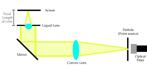
The focal length of a converging lens is the distance at which collimated light passing through the lens will be converged to a point. The focal length was measured by sending collimated light through the bottom of the lens, which focused the light onto a horizontal screen with an adjustable height. The height of the screen was adjusted until the light was brought to a focused point, and the distance in between the lens (measured from the plane of the iris opening) and the surface of the screen was measured to determine the focal length.
The collimated light was produced by sending light from an optical fiber source through a 500µm pinhole to create a point source. All light given off by a point source in the focal plane of a converging lens will exit the lens as parallel light, so a converging lens with a focal length of 15cm was placed 15cm away from the point source, which created a beam of collimated light that was deflected upwards through the lens by a plane mirror.
Microscope
Incorporating the lens into a simple (single lens) microscope allowed it to be used effectively, since the lens could remain horizontally level and stable, reducing aberrations due to gravity. The variable focal length of the lens could be used to shift the focal plane, and was used to bring the image into focus on the CCD element of a computer camera. The microscope was composed of a light source, micrometer-mounted stage, droplet lens, and an Electrim 1000N CCD computer camera. This setup was very similar to the setup used for the focal length measurement - it simply replaced the screen with the CCD camera, and added a slide holder underneath the lens to hold a sample to be imaged. The benefit of the camera used is that it is a true computer camera (not just a video camera); this means that each pixel of the CCD element corresponds directly to a single pixel of the output image.
The simple microscope used the liquid lens as its only magnifier. Light entered the setup by reflecting off a plane mirror below the slide holder and lens. The object was placed below the lens, and the light passed through the lens, creating a real, enlarged image on the surface of the CCD element of the camera.
The camera contains a rectangular 652x494 pixel CCD element, with each pixel measuring 7.4 µm X 7.4 µm. The corresponding output images have the same pixel resolution, allowing components of the image to be roughly measured using a pixel count. These pixel sizes give the dimensions of the image on the CCD element and remove the factor of magnification from the camera onto the monitor display. With an object of known size, the magnification of the lens can be easily calculated by comparing the image size on the CCD element and the object size.
Procedures and Results
Focal Length Measurement
Given the nature of the lens, the focal length was strictly dependent on the diameter of the iris as long the volume of water in the drop remained constant. The relationship between the drop's diameter and focal length was measured by observing the distance at which light was brought to a focus for a given diameter.
The opening of the iris (diameter of the drop) was controlled by a small lever that moved over a range of approximately 88 degrees. By measuring the opening of the iris for a given angle of the lever, the linear relationship between the lever's angle and the diameter of the opening was established, shown below. This allowed the drop's diameter to be interpolated using the position of the lever, since measuring the actual drop using a pair of calipers would be too difficult and would risk contacting the drop itself. The angle measurements (from 0 to 88) were taken from the position at which the iris was fully open.

Note: At 0 degrees, the iris is not fully closed: the angle
measurements were taken from the point
at which the iris was fully open,
and was brought 88 degrees down.
In order to measure the position of the lever, the iris itself was mounted onto a rotating stage with angle markings.
The focal length of a converging lens is the distance at which collimated light passing through the lens will be converged to a point. The focal length was measured by sending collimated light through the bottom of the lens, which focused the light onto a horizontal screen with an adjustable height. The height of the screen was adjusted until the light was brought to a focused point, and the distance in between the lens (measured from the plane of the iris opening) and the surface of the screen was measured to determine the focal length. The focal length of the lens was plotted with respect to lens diameter.
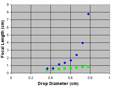
The green points indicate the focal length of a spherical water drop of equal diameter.
As the diameter of the drop increases, its shape clearly deviates considerably from a sphere.
The collimated light was produced by sending light from an optical fiber source through a 500µm pinhole to create a point source. All light given off by a point source in the focal plane of a converging lens will exit the lens as parallel light, so a converging lens with a focal length of 15cm was placed 15cm away from the point source, which created a beam of collimated light that was deflected upwards through the lens by a plane mirror.
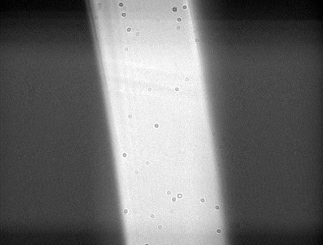
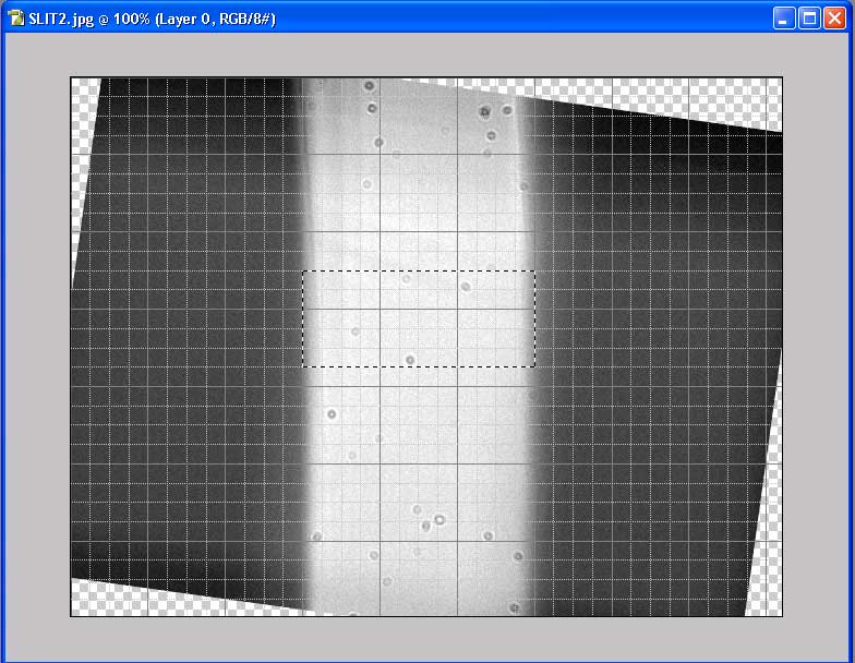
Imaging a narrow slit
The first object imaged was a metallic slit known to 150 microns in width. As shown in these figures, the image captured with the CCD camera was rotated and aligned to a grid in Photoshop, allowing the width of the slit's image to be measured in pixels. The slit measured approximately 210 pixels across. Each pixel corresponds to 7.4µm on the CCD, which means that the image of the slit on the CCD was 1554µm wide. The magnification is defined as the image size divided by the object size, so this was 1554/150, or approximately 10X. The diameter of the water lens for this measurement wasn't recorded.

Images from the CCD and liquid lens were captured. Dimensions of the
images were taken in pixels,
and converted to the actual image size on
the surface of the CCD element.
Imaging a diffraction grating
A diffraction grating was also imaged using the microscope. In
order to measure the slit spacing, a beam from a green laser pointer
(λ = 532 nm) was sent through the grating, and the diffraction
pattern was measured. Using the formula:
d sinθ = mλ
where d is the slit spacing,
m is the order of the
maximium (the distance to the 8th order on either side was measured,
22.9cm in total, then
divided by 16 to calculate a more accurate 1st order distance - 1.43 cm),
λ is the wavelength (532 nm),
and
sinθ is the distance of the m order maximum from the principal
maximum over
the distance from the grating to the screen (using the paraxial
approximation, sinθ ~ θ, and θ ~ tan θ).
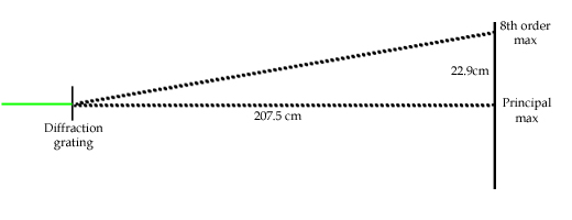
d(1.43x10^-2/270.5x10^-2)=532x10^-9
d=1.0063x10^-4 meters,
the slit spacing of the grating was determined to be approximately
100µm
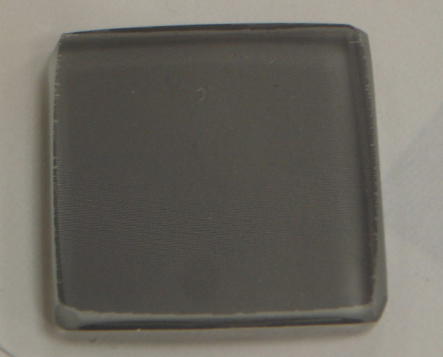
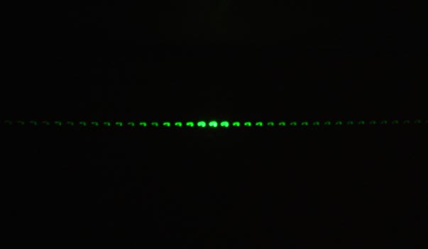
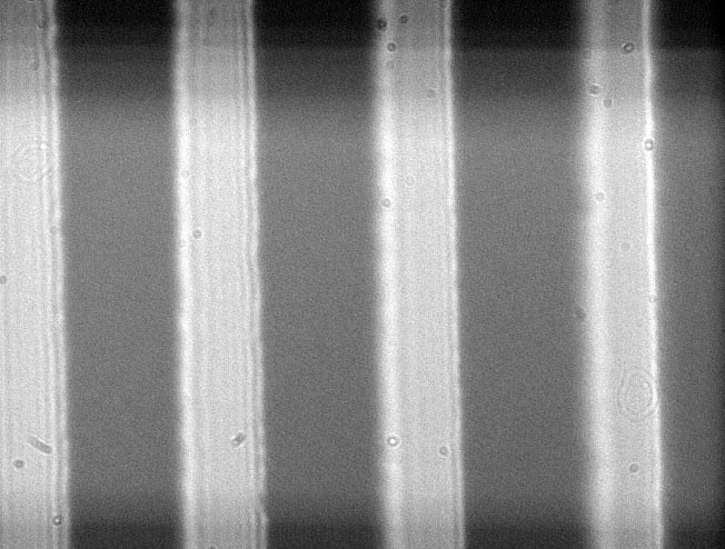
Shown here are images of the diffraction grating, the diffraction pattern
produced
through the grating, and an image of the grating under the liquid
lens microscope.
References
- Kira Schultheiss' Report on Ball Lenses
Institute of Materials Research and Engineering - A Pressure Controlled Liquid Lens
Philips Research - Electrowetting Liquid Lens
Varioptic - Electrowetting Liquid Lens
Brian J Ford's Leeuwenhoek Microscopy Page
Explanation of Simple Magnifiers