What is a wave?
A wave is traveling energy in a medium. The individual particles that
make up a wave are not moving in a particular direction. They are just
oscillating back and forth in time. There are 2 types of
waves which are described extremely well here
How Does Light Propagate?
A light wave is transverse but it is not made up of individual
particles. So then the question becomes where does the energy of a light
wave come from if there are no particles to oscillate. The energy comes
from electric and magnetic fields which are both present and oscillate
perpendicular to direction the light wave travels in. They interact in
such a way to propagate energy. Light thus is known as electromagnetic
radiation and the simplest light wave is called a plane wave.
How can a Plane wave be described?
The electric field of a plane wave shown here can be described by the
equation E(x,t)=Acos(kx-wt+p). Where the wave is traveling in the x
direction through time. The period given by T is the length of time of
one cycle of the wave. w is the temporal frequency of the wave(how many
cycles occur in 2pi radians). The equation is w=2pi/T. The wavelength
given by lamda is the physical length of one cycle in meters. K is the
spatial frequency of the wave (how many waves that occur in 1 meter). The
equation is k=2pi/lamda. The P is the phase shift of the wave which makes
it a more general sinusoid. The A is the amplitude of the wave.
What about a Spherical Wave?
A spherical wave is another type of wave. An example of one is if you
throw a rock into a pond the ripples in the water come from the point
where the rock landed and spread out. The same idea is true of light
waves from a point source. The light travels in all directions as if a
plane wave was emitted simultaneously in every direction. The electric
field equation is given by E(r,t)=(Acos(kr-wt))/r where the wave is
traveling in the radial direction though time with a decreasing amplitude
proportional to r(the distance from the point source).
Describing Waves in Complex Notation
Waves can be described in coplex notation instead of sinusoidal in
order to make some mathematical derivations much simpler. For example,
through euler's formula cos(x)=Re(e^(ix)), so a plane wave can be written
as E=Ae^(i(kx-wt+p) with the understanding that only the real part is
needed. A similar equation can be written for a spherical wave.
The Concept of Interference
What happens when two waves overlap with each other? Interference will
occur. If they add in phase to double the amplitude it is constructive
interference and if they add out of phase to completely null out the wave
it is destructive interference.
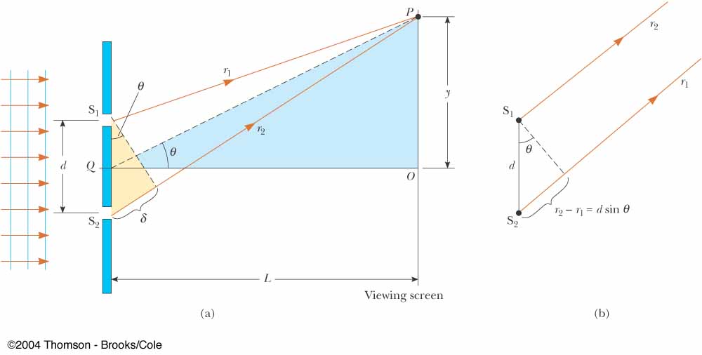
Two Slit Interference
Thomas Young's two slit interference experiment(shown below) involves a plane wave incident on a wall with 2 small slits a distance d apart. Each slit acts as a point source to create two spherical waves. A screen is placed a distance L away from the slits. There will be a light and dark pattern on the screen because the two waves are interfering with each other. When the difference in distance from a point on the screen to each slit is an integer multiple of the wavelength then the waves will interfere constructively at that point. So there is a bright spot. So when r2-r1=n*lambda, where n is an integer there will be a bright spot. Using an approximation that L is very far away and much bigger than d, you can find by geometry that r2-r1=d*sin(theta). So the location of the bright spots is given by d*sin(theta)=n*lambda.
Can the entire interference pattern at the screen be described mathematical?
Each spherical wave's electrice field can be desribed by the spherical wave equation. So the field from point S1 is given by
E1(r,t)=(A*e^(i*(k*r1-w*t+p))/r1 and the field from point S2 is given by E2(r,t)=(A*e^(i*(k*r2-w*t+p))/r2. Quantities A,k,w,p are the
same in both because both spherical waves came from the same plane wave source. Now, the electric field at the screen is given by
E=E1+E2 at the x=L, where the x-axis is horizontal and the y-axis is vertical. However, our eyes and all of our detectors do not see
electric field. We see intensity(I) instead which is given by I=(magnitude of electric field)^2=|E|^2. So the intensity at the screen
is given by I=|E1+E2|^2. As Stephanie showed in her complex number lecture |z|^2=z*z#, where z# is the complex conjugate of z. So
I=(E1+E2)*(E1#+E2#)=E1*E1#+E2*E2#+E1*E2#+E1#*E2=I1+I2+E1*E2#+E1#*E2. I1 and I2 are the intensities of the each individual spherical
waves and the last two terms are the interference terms. Now you would plug in directly for E1 and E2 and simplify. The math is too
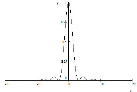
complicated to go through here so I will just tell you the final intensity assuming that I1=I2=Io and assuming the far-field
approximation that L>>d. I=4*Io*cos^2(k*d*y/(2*L)). A graph is shown here. So ideally, the bright spots do not lose amplitude as y
increases. Also, from this equation the location of the bright spots can be derived by setting the argument of the cosine equal to
integer multiples of pi which is where cos^2 is at its maximum. Doing so, along with some geometry, gives d*sin(theta)=n*lambda which
is exactly what we got above!
What about interference from more than two slits?
Lets consider what would happen with a plane wave incident on 4 slits. Again, each slit acts as a point source eminating a spherical wave with an interference pattern located on a screen a distance L away shown here. The brightest spot occurs when all four of the waves add constructively. There also are places however where three of the waves interfere constructively and the 4th destructively with the other three. So, there will be a bright spot but not as bright as when there all add constructively. So, it turns out that the interference pattern will have big peaks as well as little peaks as the location on the screen is changed. Here is a plot of several multislit interference patterns. Notice the number of smaller peaks increases with the number of slits and the distance between maximum peaks also increases although that isn't clear from the picture.

What if the number of slits approaches infinity within a finite distance?
The first thing to realize is that one slit with a finite width d and an infinite number of slits within a distance d are equivelent statements. Intereference of an infinite number of slits over a finite distance is known as diffraction. A plane wave travelling through a slit diffracts(interferes with itself) and the behavior is the same as if there were an infintite number of point sources caused by an infinite number of small slits. This is known as Huygen's Principle. So what would the intenstiy pattern look like from an infinite number of spherical waves interferering at a distance L away? There will be a maximum peak in the center as well as smaller peaks as the distance from the center increases just as with a few slits. However, a second maximum peak will never be reached, because with an ifinite number of waves they all can never add constructively except for at the center. The distance between maximum peaks increases as the number of slits increases so now the next maximum peak is at infinity. The intensity pattern for diffraction through a single slit is shown below. Below that is an actual picture of the single slit diffraction intensity pattern.

Can this this diffraction pattern be represented mathematically?
There is a long mathematical derivation of the intensity pattern involving Fourier Transforms that would be too much to discuss here. The end result is that
I(y)=c^2*d^2*sinc^2(y*d/(lambda*L)). Where c is a bunch of constants that come out of the math, d is the length of the slit, lambda is the wavelentgh, L is distance from
the slit to the screen, and y is the position along the screen. The function sinc(x)=sin(pi*x)/(pi*x). This makes sense because the pattern looks like a decreasing
sinusoid with a maximum at y=o.
Why isn't there diffraction in each of the slits in Young's two slit experiment?
Well, there is diffraction in the small slits, but the slit width is chosen to be small enough so that only the central part of the diffraction pattern is relevant. The first zero would be at a really large y. Also, for a small width the diffraction pattern looks basically spherical which is why they are approximated as spherical waves. It turns out that if the slit width is approximately equal to the wavelength of the incident light then this approximation can be made.