An Introduction to Spatial Light Modulators
I. What is an SLM?
A spatial light modulator (SLM) is a transmissive or reflective device that’s used to spatially modulate the amplitude and phase of an optical wavefront in two dimensions.

General Applications:
Optical Correlator: a device used to compare the resemblance between two optical signals using their Fourier transforms
The Fourier transform of the input beam is multiplied by a stored Fourier transform in the Fourier plane. If the input and reference patterns match exactly (i.e. the stored transform is an exact complex conjugate of the transform of the input), a second Fourier transform will lead to an autocorrelation function containing a sharp peak (i.e. a well focused spot of light in the output plane). If the input and reference patterns don’t match, the second Fourier transform results in a cross-correlation function, which has no sharp peaks.
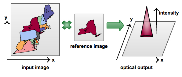
An optical correlator can also pick out matches from cluttered or partial data, with an appropriately sized peak according to the strength of the match. The SLM could be used as an input beam or in the Fourier plane as the reference, either way searching through thousands of 2D data patterns each second.
Projection system: display systems that are brighter and more efficient than those that use a cathode ray tube system
SLM-based projection systems can overcome the limitations of using three cathode ray tubes (which are costly, limited in brightness, and require precise adjustments). Three separate SLMs modulate the amplitudes of the readout beams (red, green, and blue inputs), which are then combined to produce and project the image.
Optical crossbar switch: device used to efficiently reconfigure connections between transmitting and receiving ports using a binary thresholding mode
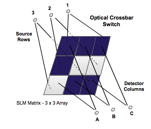
A binary optical matrix processor will either block or transmit source input points to each element of an NxN matrix mask. The SLM can then rapidly rearrange interconnects between N transmitting ports and N receiving ports, in a manner that doesn’t affect the other interconnects. The source/detector configuration ensures that any input can be channeled to any output, which important applications in broadcasting.
Optical elements: items used in optical setups for beam shaping (e.g. axicon lens, wave plates, gratings)

Image Source: Arlt, Dholakia 2000 SLMs can be programmed to produce light beams with various optical wavefronts by taking the place of conventional optical elements. For instance, they can be used to create optical vortices and higher order Bessel beams, which both have an azimuthal phase variation.
II. The Addressing Mode
The addressing mode refers to the type of input signal that controls the optical properties of the SLM. It contains information regarding how the incident light beam should be modified.
Optically-addressed – one light beam (the optical control beam) is used to change a variable associated with another light beam (the incident beam); the optical control beam is often called the “write beam” and the incident beam is the “read beam”
Electrically-addressed – an electric signal is used to change a variable associated with the incident light beam; this will often be computer generated
III. The Modulation Mechanism
The modulation mechanism refers to the intermediate step between addressing the SLM with an input signal and actually altering the incident light beam. There are various methods by which the information from the input signal is passed on to a modulation material, which then interacts with incident light.
Mechanical – the modulating material is macroscopically deformed by the write signal to physically block or alter the read light beam.
Electrooptical – the write signal causes an electric field, which affects the modulation material
liquid crystal (discussed below)
Thermooptical – the optical properties of the modulating material change because certain characteristics of the material are temperature dependent
Magnetooptical – a modulation material with a permanent magnetic dipole moment is altered from the write signal creating a magnetic field
IV. Electrooptical Liquid Crystal SLMs
One of the most commonly used modulation mechanisms today is the electrooptical spatial light modulator containing liquid crystals as the modulation material. The optical properties of the liquid crystals are modified by means of an electric field.
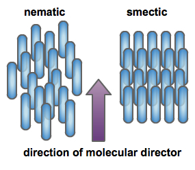
Liquid crystals are rod-like molecules that are in a state of matter between a liquid and solid. Like a solid, they have an orientation order, where the long axis of each molecules is oriented in the direction of what’s known as the molecular director. Similar to a liquid, the molecules are usually randomly positioned in what’s known as the nematic phase. In the smectic phase, these molecules are arranged in well-defined planes.
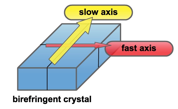
Another important quality is that, similar to many crystalline materials, liquid crystals are birefringent, meaning they have different indices of refraction associated with different crystallographic directions. This is because the binding forces that form the crystal are anisotropic, i.e. the atoms have stronger forces holding them together in certain crystalline directions. The long axis of the molecules is known as the slow axis, where rays experience a higher index of refraction and are therefore bent more.
One of the biggest distinguishing qualities of liquid crystal spatial light modulators is the type of microdisplay that is used to collect and modulate the incident light – either transmissive (LCD) or reflective (LCOS). A second distinguishing characteristic is the alignment of the liquid crystal molecules, which is typically either a parallel, vertical, or twisted formation. This determines which variable(s) of the incident light beam can be altered – either phase only, or amplitude and phase.


Optically-Addressed PAN LCOS
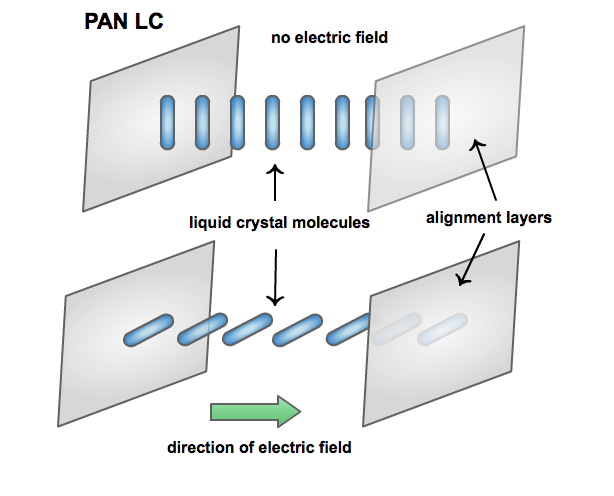
One example of a reflective SLM is the optically addressed PAN (parallel aligned nematic) LCOS (liquid crystal on silicon). The liquid crystal molecules are aligned parallel between two alignment layers (typically polyvinyl alcohol). When an electric field is applied, the crystals tilt in the transmitting direction of the light beam to align themselves with the field. Due to the liquid crystal’s birefringence, the light beam undergoes a phase modulation based on the relative orientation between the LC molecules and electric field.
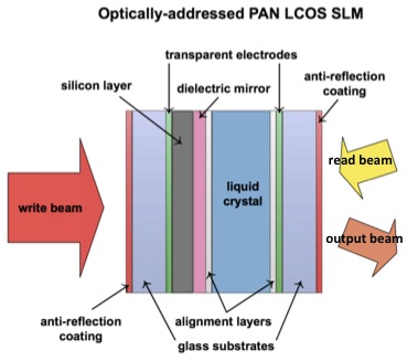
The optical write-beam will form a certain intensity pattern on the
silicon layer, based on the type of optical wavefront that is desired. In
the areas where the light is more intense, the silicon’s resistivity
decreases, which allows more voltage to pass through to the LC cell. This
will increase the strength of the electric field, causing a greater tilt
in the LC molecules, which in turn means a larger phase modulation of the
read-beam.
Electrically-Addressed TN LCD
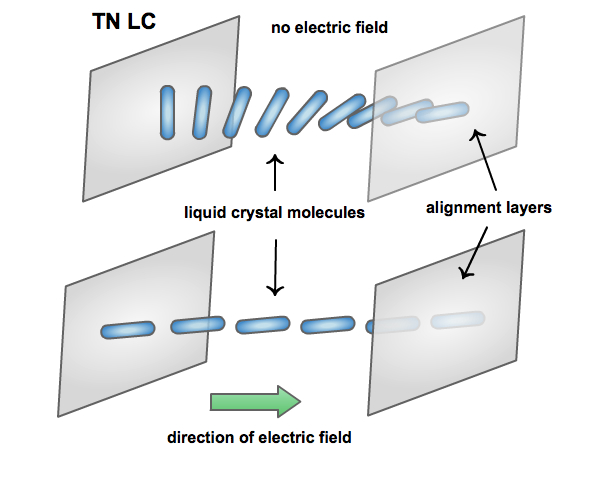
An example of a transmissive SLM is the electrically addressed TN (twisted nematic) LCD (liquid crystal display). In these LC cells, the molecules are aligned between two alignment layers in a helical twist, with the first and last molecule perpendicular to each other. Each cell (i.e. pixel) can experience an electric field across it due to a video signal from the computer. This again causes the LC molecules to align themselves in the direction of the field. The relative orientation of the molecules and their birefringence property cause a phase modulation, however this time we can also perform amplitude modulation by including two polarizers in the setup.
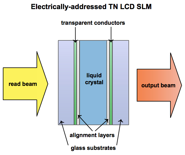
When there’s no electric field, the light that’s incident on the cell will initially have a polarization axis parallel to the cell’s entrance face. The helical alignment of the LC molecules causes the lights polarization to rotate as it propagates through; the polarization axis of the output beam is therefore perpendicular to the original direction. A polarizer at the exit face that’s oriented parallel to the original direction blocks light from being transmitted. When there is an electric field, the incident light will not undergo a polarization rotation, therefore light will be able to propagate through the polarizer at the exit face.
One of the issues with transmissive SLMs is that they often have a
small pixel
fill factor (around 50%), which refers to the pixel’s percentage of
light sensitive material. The relatively large amount of optically
inactive space often causes extra, undesirable diffraction orders to
appear in the output.
Liquid crystals and polarization rotation
Why do the liquid crystal molecules in a twisted nematic alignment rotate the polarization of light (i.e. how a liquid crystal molecule’s “tilt” changes the phase of an incident beam and it’s “helical alignment” rotates the polarization of an incident beam)?
If light enters a liquid crystal molecule with its polarization axis parallel to the slow axis of the molecule this extraordinary ray will be slowed down; the rays will travel faster when the polarization axis is perpendicular to the slow axis. Therefore, phase modulation occurs as the liquid crystal molecule is tilted from having the polarization axis of incoming light parallel to the slow axis to perpendicular to the slow axis.

This can be seen in the parallel-aligned nematic liquid crystal, where the molecules begin in an upright position and then tilt towards the direction of the electric field at an angle θ in the longitudinal (y-z) plane. The stronger the electric field, the more the tilting angle increases in the direction of the axis of propagation, and the more the phase is modulated.
On a much smaller scale, Rayleigh scattering occurs between the electric field of the incident light beam and the electrons of the liquid crystal rod-like molecule. This is a type of elastic light scattering, in which negligible energy is transferred and therefore the wavelength of the incident photon is conserved – only the direction changes. Since these electrons are bound to the crystal, scattering occurs along the axis of the rod.
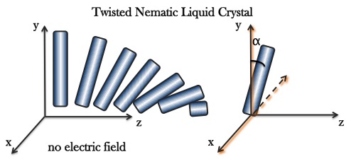
In a twisted nematic liquid crystal, where the molecules are aligned in a helical fashion, the scattering causes light’s polarization axis to follow the helix. Since each molecule is tilted away from the longitudinal axis (in the transverse x-y plane) by a certain angle α, the polarization of incident light will be rotated by an angle α as it exits the molecule.
V. Conclusion
Spatial light modulators are used to spatially modify an optical wavefront in two dimensions. The most commonly used models are electrooptical with liquid crystal molecules used as the modulation material; the alignment of these molecules and their birefringence make it possible to modulate the amplitude and/or phase of an incident light beam. Reflective SLMs are high quality devices, however they can be quite expensive; the alternative is transmissive SLMs, which tend to have extra diffraction issues but are much more affordable for a teaching lab. Spatial light modulators in general have a variety of interesting applications in industry and research.
References
“Spatial Light Modulators.” Holoeye Photonics (2013).
Arrizón, V. "Complex modulation with a twisted-nematic liquid-crystal spatial light modulator: double-pixel approach." Opt. Lett. 28 (15), 1359-1361 (2003).
Boruah, B. R. "Dynamic manipulation of a laser beam using a liquid crystal spatial light modulator." Am. J. of Phys, 77(4), 331-336 (2009).
Durand, G., Leger, L., Rondelez, F., Veyssie, M. Quasielastic Rayleigh Scattering in Nematic Liquid Crystals Phys. Rev. Lett, 22(25), 1361-1363 (1969).
Huang, D., H. Timmers, et al. "A low-cost spatial light modulator for use in undergraduate and graduate optics labs." Am. J. of Phys, 80 (3), 211-215 (2012).
Li, F., Mukohzaka, N., et al. "Phase Modulation Characteristics Analysis of Optically-Addressed Parallel-Aligned Nematic Liquid Crystal Phase-Only Spatial Light Modulator Combined with a Liquid Crystal Display." Opt. Rev. 5 (3), 174-178 (1998).
Neff, J.A., Athale, R. A., and Lee, S. H. “Two-Dimensional Spatial Light Modulators: A Tutorial,” Proceedings of the IEEE, 78 (5), 826-855 (1990).
Also see Azure's paper, "Twisting light with twisty molecules," 2004.