The Geometry of Sunlight
Marissa Romano
Laser Teaching Center
Stony Brook University
Introduction
My mentor, Dr. Noé, concluded one of our first meetings by showing
me how the shadow of an object becomes increasingly blurred with
increasing distance, as shown in this picture of a
flagpole shadow.
Although I have seen this effect almost every day I had never thought
about why this happens.
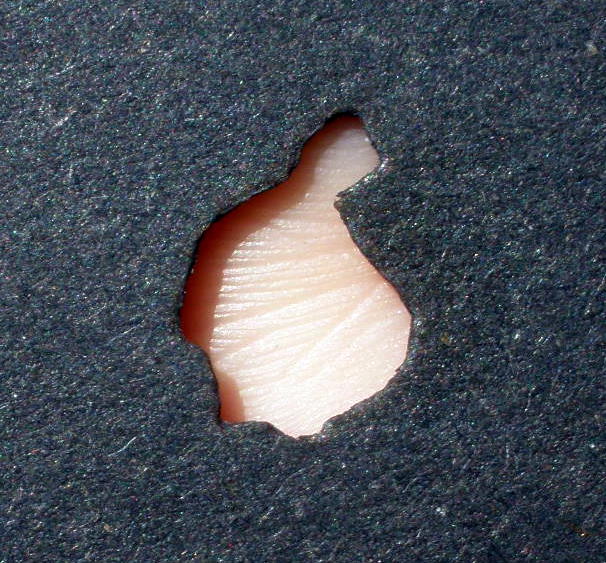
To help me find an explanation he showed me a related phenomenon. He let
some sunlight pass through a small hole made with his hand and pointed out
that the disk of light projected onto a piece a paper grows in size as the
paper is moved further and further away. I estimated that the diameter of
the disk was about 1, 2 or 3 cm at about 1, 2 or 3 meters away.
He then used a small pocket mirror to illustrate that the size of a spot
of reflected sunlight also increases with distance in a similar way. When
the spot was directed to the wall between the physics and math buildings
it was about 30 cm in diameter, much bigger than the 6 cm mirror.
That evening I thought about what I'd seen and came to the conclusion that
the observed spreading of sunlight must be due to diffraction. I
drew diagrams like this one and was completely convinced of my reasoning.

It's Just Geometry !!
At our next meeting Dr. Noé suggested I think about light rays (geometry) instead of waves (diffraction) and had me draw this diagram.
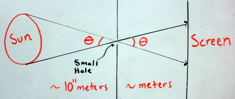
This diagram makes it clear that sunlight enters the pinhole at slightly different angles and this causes the "spreading" effect after the pinhole. The angular spread is just due to simple geometry of light rays and has little or nothing to do with diffraction. The earlier estimation that the image is 1 cm in diameter at 1 meter away is actually the angular spread of the sunlight. Similarly, sunlight reflected off a small mirror diverges, therefore resulting in a larger spot of light on the wall or screen with increasing distance.
Geometry also explains why shadows blur.
A majority of the sunlight is blocked out by the object causing a defined
dark shadow to be projected behind the object. As the object's distance
from the screen increases a small amount of sunlight is able to "get
behind" the object. The intensity (brightness) of this amount of sunlight
is less than what a person would observe in unobstructed sunlight
producing a "fuzzy" outline.
Angular Size and Time
The angular spread of sunlight is also known as the sun's angular diameter and can be determined using simple geometry. From the small angle approximation the sun's angular size is its diameter divided by its distance from the earth, therefore the esitmated angular size is 1/100 radians.
Dr. Noé and I then decided to experiment further with the angular size of the
sun. First we calculated the estimated time for the sun to move its diameter across
the sky. Since we know that 1/100 radian is equivalent to 0.5 degree and that there
is a total of 360 degrees in a day, we can say that this is proportional to a certain
time, t, in a day[1440 minutes]. In fact, angular measurements can be expressed in
units known as an
arcminute
and an arcsecond which are 1/60th of a degree and 1/60th of an arcminute
respectively. Our calculated t is equivalent to 2 minutes, thus we estimated that it
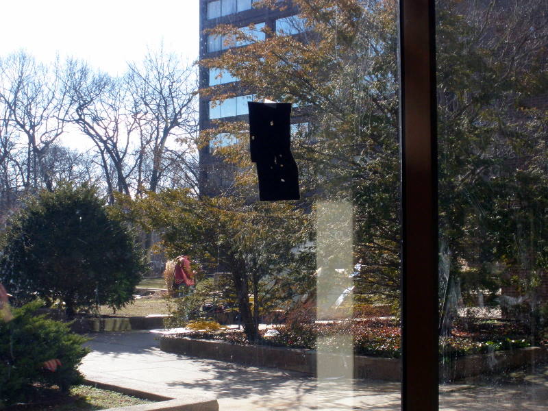
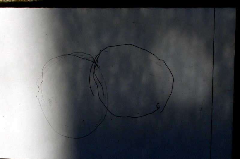
took 2 minutes for the sun to move its own diameter. To observe this quantative
result, we went into a hallway that allowed in a lot of sunlight and taped a black
sheet of paper with a hole to the window. The sunlight entered
through the hole and was projected as a circular image onto a white piece of paper
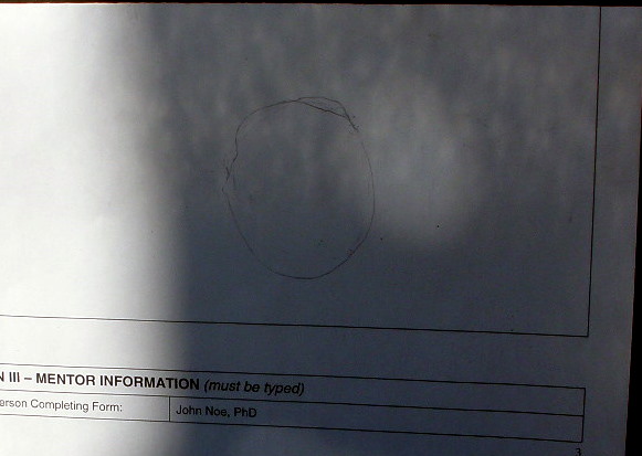
several meters away. The initial image's outline was traced and after 2 minutes the
image moved a certain distance and its outline was traced again. Our quantative
estimate was similar to the results we observed: the sun moves its own diameter every
2 minutes.


Measuring Angular Size
As mentioned previously, when sunlight is reflected off a mirror the size
of the image increases with increasing distance. In this part of the
project we made careful measurements of this effect and compared these
to the known angular size of the sun.
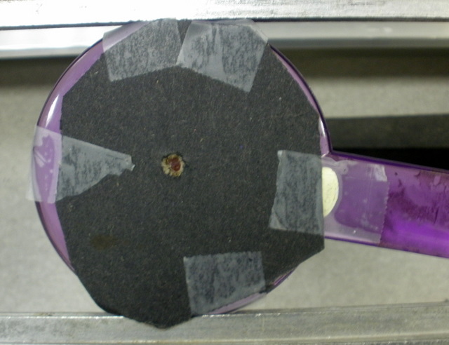
We started by covering a pocket mirror with black paper that had a small
hole (~ 3 mm diameter) poked into it with a pencil. We secured the mirror
to an adjustable stand for stability and placed the stand on the floor in
the hallway facing towards the sun.
To measure the image diameters, we created a measuring template in xfig
with six concentric circles ranging from 5 to 30 mm in diameter. (Here's
the xfig code for it.) When the template was
printed, we noticed that each diameter was off by the same factor and took
this into account when we plotted the data. For example, the 30 mm circle
is actually about 28.7 mm.
To make the measurements, I held the measuring template in the path of the
reflected sunlight. I moved the template until the image matched the
diameter of one of the circles and held this position whileDr. Noé
measured the image distance with a tape measure. We repeated this for
each circle.


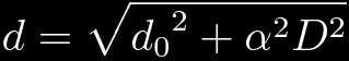
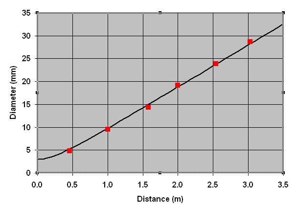
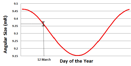
To analyze our results, we created a plot of image diameter (d) versus image distance (D) in Excel. The six measured points are shown in red in the graph below. The black line is a prediction based on the known angular size of the sun at this time of year, α = 0.00928 radians. (Changing the size of the hole lets us shift the prediction curve. Parameters of a 2.5 mm hole coincide with an α of 9.36 mR, thus giving the best fit for the ideal α of 9.325 mR.) At D = 0 the diameter of the image (d) and the hole (d0) is the same, so we assumed the prediction could be represented by a hyperbolic function:
The seasonal variation of α due to the earth's elliptical orbit is shown below. Our measurement was made on March 12th.
Partial and Total Shadows
As Dr. Noé and I explored the geometry of shadows, we naturally got into a
discussion about partial and total eclipses. A total solar eclipse can happen because
the moon shares
the same angular size
as the sun, therefore allowing it to "cover" the
sun. A total eclipse also depends on the position of the observer and time of the
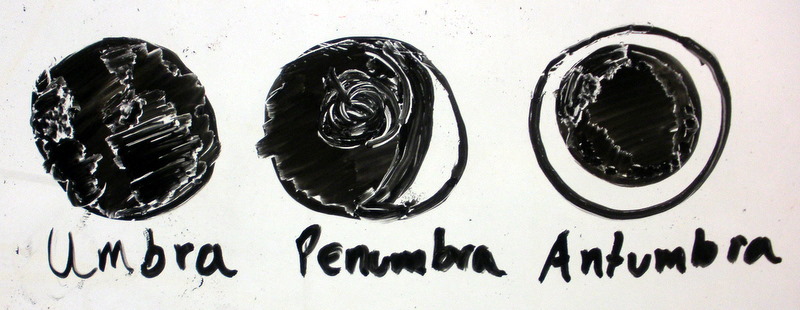
year. There are distinct parts of a shadow called the umbra and the penumbra. The
umbra is where an observer must be positioned to see a total eclipse/shadow and the
penumbra is where an observer can only see a partial eclipse/shadow. There is also
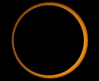
another section called the antumbra where an observer sees the moon/object with a ring
of light around it
(
an annular eclipse
).
Both Dr. Noé and I were curious if there was a
distinct dividing line between the umbra and antumbra, and as a result we attempted an
experiment that simulated a solar eclipse. We held a coin in the sunlight and its
shadow was casted onto a piece of paper. I proceeded to move the paper further away
from the coin and we looked carefully for the transition from the penumbra and
antumbra. At this specific division we expected to see a lighter area within the
shadow, but unfortunately this was too difficult to observe. The experiment was still
a great introduction to total and partial shadows.

http://apod.nasa.gov/apod/ap100122.html
Demonstrating Diffraction
In this project we have shown that the spreading of sunlight is
not due to diffraction. Diffraction requires a coherent light
source, such as a laser. To demonstrate diffraction we aimed a red HeNe
laser beam through a pinhole 0.2 mm (200 μm) in diameter. On a screen
3 meters away from the pinhole, we observed an enlarged spot of light
about 1.5 centimeters in diameter surrounded by faint concentric
circles. From the small angle approximation the angular size of the
central spot is therefore about 1.5/300, or 5 milli-radians.
The angles involved in diffraction effects are approximately given by
λ/d, wavelength over aperture size. This predicts a diffraction
angle of 0.633/200 or about 3 milli-radians, in rough agreement with the
observation.
Conclusion
The behavior of sunlight when it passes through an aperture can be
explained through simple geometry relating to the angular size of the
sun.
Although we used a simple method of measurement, its sensitivity allowed
us to observe the seasonal variation of α and record measurements
in very good agreement with our prediction.
We used another effective method to observe the sun's movement across the
sky that further related with the sun's angular size.
Acknowledgements
I have a found out that a simple topic such as the geometry of sunlight can become an extensive project where one can learn the basics of doing research.I would like to thank Dr. Noé for investing a large amount of his time to helping me. Without him as a mentor I would have little guidance and resources to perform our experiments and perfect the outcome of this report. Most importantly, he encouraged critical thinking and never just simply handed me the answers to my questions. I look forward to working with Dr.Noé on future projects, and I am enthusiastic about what we will come up with together.