Research Journal
Friday, 3 August 2012
All the research of the REUs was interesting and well presented. I think because of the City College visit, Jon, Melia, and I felt little to no anxiety in giving our presentations. Jon's pictures were stunning and left everyone impressed. Melia also did a great job in explaining all her work in such a short time-frame. I'll be continuing my work here at the LTC after my trip to Italy and also throughout the school year.
Thursday, 2 August 2012
We are done working on our final preparations for the presentations tomorrow! I've been practicing a lot from the notes I've written. Since, I don't have definite results, choosing my words carefully is key. It's important that I remember exactly what I am going to say, so that the audience clearly understands what I've done this summer.
Wednesday, 1 August 2012
The practice presentations today helped me to realize what needed to be edited for Friday. There's a lot that needs to be cut out because of its redundancy, and I also need to add some diagrams to make my point clear. Currently, I don't feel too well, but I'm trying my best to fine tune this presentation as best as I can. Hopefully I'll be better tomorrow.
Tuesday, 31 July 2012
After working with the setup for quite some time, I found using a pair of lenses (f= 35 mm & 750 mm) worked best for the table space. I didn't understand why I was getting such a distinct Airy pattern, until Dr. Noe told me to use a pinhole (75 microns) and an iris diaphragm to clean up the incoming beam. After going through the axicon lens, I used a polarizer to reduce the intensity so I could take a proper picture with the CCD. The result was a zero order Bessel beam!
Monday, 30 July 2012
The axicon lens has arrived! I immediately tested it out with the LG beam from the open-cavity HeNe laser, but with little success in seeing anything clearly with the CDC. I thought I saw something that looked like circular rings, so I have high hopes for tomorrow when I expand the beam more with a telescope!
We also finished fine-tuning our abstracts. We have yet to submit them to Michal Simon, but we will do so tomorrow after taking one last look! It's a little nerve-racking knowing this is due by tomorrow evening (five o'clock).
Friday, 27 July 2012
We had another discussion similar to that about the two slit diffraction.
This time we described a general case using Fourier methods and we were
able to get a final expression for the Fourier transform of the aperture
function (which is the Fraunhofer intergral)! So the corresponding
intensity can be represented by:
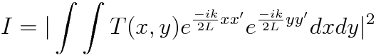
where L is the length in the z-direction, x & y are points on the aperture, x' & y' are points on the screen, and T is the transmittance of the aperture.
Thursday, 26 July 2012
Looks like I'll be using the axicon lens to get some data! Tomorrow, Jonathan is leaving early to drop by City College to pick it up from Giovanni. I'm actually pretty excited to see and use this elusive optical instrument!
Wednesday, 25 July 2012
Today, I went to the Math/Physics Library to find books on acousto-optics and acoustic waves in general. I decided to check-out J. Sapriel's Acousto-Optics and Morfey's Dictionary of Acoustics. The latter is a quick reference guide to help me with new terms I come across as I read articles, papers, and the new book I just got.
I also started writing my abstract for the summer REU program. Although I have yet to experiment with the TAG lens, I will still be using it as the center of my discussion! I'll definitely continue on with my research once (or if) I receive it from TAG Optics.
Tuesday, 24 July 2012
The optical fiber setup is once again grabbing my attention. I decided to fool around a bit with it and collimate the output of the fiber. I then added the AOM on the end of the configuration. I need an rf amplifier to drive the AOM, so I started just by playing around with an rf signal generator and an oscilloscope. The digital display on the signal generator, which I thought was simple, is a bit confusing and likes to jump around randomly (aka I have no idea how to use it). Maybe I'll continue to look at it tomorrow after getting some literature on acousto-optics from the upstairs library.
Monday, 23 July 2012
While waiting for a response from the CEO of TAG Optics, I've been reading several papers (two of which are from Giovanni) on Berry phase, gauge theory, and fiber bundles. Some of it is a little unrelatable to me because of its highly theoretical nature, but I'm really starting to grasp the concept of geometrical phase!
Friday, 20 July 2012
Dr. Noe began writing a draft for an e-mail in response to Christian Theriault. So far, he wrote a decent amount on how the LTC is a learning laboratory that provides students with the tools to experiment with their interest in optics. He also explained my experience here as an undergraduate researcher last semester and my current participation this summer's REU program. I think the most important aspect of the response is to convey our genuine interest in using the TAG device and our willingness to pick it up personally if necessary. After he sends the e-mail, we'll have to wait patiently for a reply!
Thursday, 19 July 2012
Today, we traveled by car to Giovanni's optical vortex party at City College. He met us at the parking lot, where he then took us to a conference room in the physics department. In the room, there were four posters set up, and we had time to mingle with one another. Before I could ask any in-depth questions, we were asked to head down for lunch. Immediately following the lunch Giovanni generously provided us with, we returned for the beginning of the presentations. The presentations themselves varied in degrees of difficulty and concept since the audience was made up of optics experts, college students, and high school students. After every few presentations, we took fifteen to twenty minute breaks for small discussions. When it was Melia's and my turn, I no longer felt nervous. I thought the talk went fairly well, besides some mistakes I made in answering a question. Jon, although having a shorter presentation, did an amazing job in withstanding the questions of the audience; it was great to see him passionately explain his plans for his project. Our visit ended with a tour of Giovanni's lab, which was surprisingly hot and consisted of one table. The diffraction grating was by far the most interesting aspect of his "donut" setup; it was programmed on the computer and can be displayed on the spatial light modulator (SLM) at any time. One can also adjust the grating to change the topological charge of the resulting vortex.
Before returning home, Dr. Noe took us to a Greek restaurant called "Loi". Although it took a bit of searching to find, we arrived around 7:30 p.m with the intention of having a decent meal. However, after the first round of appetizers of giant lima beans, octopus, eggplant, and mussels, we quickly realized the magnitude of the cooking's quality. We then happily welcomed the main course of scallops (the best I've ever eaten), salmon, dandelion greens (horta), beets, and mixed roasted vegetables. To finish, we ordered baklava and galaktoboureko for dessert. Along with receiving an amazing meal, we were also greeted by the owner, Maria Loi. The impressive nature of the restaurant only increased when, according to Dr. Noe and Jon, there was wonderful music playing in the men's bathroom. It was a perfect end to an optical vortex party for sure; my head is still spinning!
Wednesday, 18 July 2012
Michal Simon gave the REU students a presentation today on non-redundant masks that he uses in his astronomical interferometry setups. He went over the topics of adaptive optics and correcting the effects that the atmosphere has on incoming light from far-off stars and planets with a deformable mirror. His methods, however, involve an interferometry technique using non-redundant masks (aperture mask) that are placed over a telescope's mirror. This allows for a diffraction limited telescope to be made (not perfectly of course).
Afterwards, we had our lunch meeting where Melia and I gave a quick run-through of our presentation in front of Jon, Dr. Noe, Marty, and Ariana. From this, we received helpful criticism to improve the content of slides and overall delivery. Our presentation would most likely fail to appeal to tomorrow's audience without such guidance. For the rest of the day, Melia and I put in long hours to correct and fine-tune the slideshow; Dr. Noe also helped us edit some statements that were too long or unnecessary. Hopefully, we don't lose too much sleep tonight!
Tuesday, 17 July 2012
I started looking at companies that sell piezoelectrics, such as Thorlabs, Channel Industries, and SEACOR. Channel Ind. was the more attractive company, since it had the most variety in the ceramic piezos. I was specifically looking at the thin wall hollow cylinder and striped hollow cylinder. The latter seems to drive in the radial direction (transverse OD mode), but I am unsure of why there are striped electrodes running down vertically (radially poled). I think this may have to do with the direction in which the piezo is driven.
I then suddenly received an e-mail from Christian Theriault, the CEO of TAG Optics Inc. He is considering lending us a device, but has asked for more information on my project and my goals at the LTC. I will wait for further assistance from either Marty or John before responding!
Monday, 16 July 2012
In the morning, Hal provided us with a video to watch on the Bell's inequalities. The Eberly video gave us a clear explanation that quantum cannot be fully understood because we live in a classical world. For example, we can put two marbles in a bag that are red and blue. If I take out a red marble, then I already know the other one is blue without actually observing it. Quantum mechanics obscures this reasoning, and by "measuring" the color of the first marble, the other marble is affected. So, one can never know the color of both the marbles in a quantum system. This means the only way to detect a photon is to destroy a photon. Isn't that confusingly heart breaking? This is still a bit puzzling to me, but I'm a little closer to accepting quantum's odd properties.
Eberly explained the Bell's inequalities using a classical representation
involving coins:
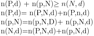
Where P&p=penny, N&n=nickel, D&d=dime, and the function n is the number of flips. Heads and tails are represented by capital and lowercase letters respectively. What is this trying to say? Let's look at the second equation. It says when you get P (penny, heads), d (dime, tails), the nickel can either be heads or tails (N or n). In the end, the number of flips is dependent only on two coins, therefore the third equation is redundant or not needed. Note how these are not probabilities, but are merely addition of numbers!
So, how does this relate to quantum? Eberly used the same principles to explain the interaction of photons and their polarizations. For the classical coin explanation, the nickel can be either heads or tails even before actually observing. However, with photons, you cannot assume that a photon is polarized in any particular direction without observing it (you have no idea if it's head or tails or both...) For quantum mechanics, this inequality fails because photons are "entangled" with one another. Like I stated before, when measuring the polarization of a photon, one destroys it. Confused? Me too.
Friday, 13 July 2012
Today, I traversed the LIRR and the subway with Melia, Kate, Joe, and David to attend a meeting with the Physics and Astronomy department at the American Museum of Natural History (AMNH). There we met a group of undergraduates taking part in research relating mostly to astrophysics. After introducing ourselves to one another, their students gave a few presentations, which were all based on an Astronomy Picture of the Day (APOD). For example, the first presentation was about the Mars rover, Opportunity, and it lightly touched on its engineering, uses, and current mission. The most interesting talk, I thought, was one on light pollution. The International Dark-Sky Association is one group that tries preserving the beautiful night sky by controlling and preventing light pollution; all it takes is turning off any unnecessary lighting.
To finish off our visit, we were given 'Super Vouchers' that gave us access to any special exhibits. I chose the "Creatures of Light" and "Journey to the Stars", which were about bioluminescense and star formation respectively. I was fairly disappointed with the bioluminescense exhibit because it lacked any depth of information and explanation. It seemed it was all put into simplified terms so that all children could understand. I then left to visit a friend who was already wandering the city street (I didn't get lost!).
Thursday, 12 July 2012
I looked over more articles on the general formation of a Bessel beam. Understanding what I read is becoming much more intuitive than in the past. I know which words to focus on and when to search an external source for more information. Reading really is helping my overall knowledge on various topics.
Melia and I also started an outline for our presentation on Bessel beams for the vortex party. The whiteboard is currently covered with an organized list of main ideas and subtopics that we will be discussing in detail. Although we are far from experts in the area, I think the knowledge we presently have will suffice for a twenty minute presentation.
Wednesday, 11 July 2012
Our meeting with Michal Simon was routine. This time, I showed an image of an acousto-optic modulator (AOM) to explain the interaction between an acoustic wave and a laser beam. This then tied into my current interest in using a TAG lens to produce a Bessel beam. Jon and Melia also gave progress updates on their projects. Melia showed several graphs that compared the Gaussian beam with a Bessel beam, and Jon explained that he would be using a circular multiple pinhole interferometer (MPI) in his project that involves optical vortices.
As usual, we had our lunch meeting immediately following this to talk about our progress with Hal. We told him of our "findings" in papers, and our ideas to make a short-term project out of them. Again, I mentioned the TAG lens and Hal seemed to be as interested as I am on how it works. Coincedentally, upon returning to the LTC, I received a response from Craig Arnold telling me that the TAG lens is now a commercial product. He also encouraged me to get into touch with Christian Theriault for more information on the lenses; I did this with the hope that they would be willing to let us borrow one for experimentation. I have my fingers crossed!
Tuesday, 10 July 2012
Today, I have read several articles on Bessel beams. The articles mostly consisted of comparisons of beam types i.e. Bessel v.s Gaussian. Unlike a Gaussian beam, a Bessel beam is non-diffracting (does not diverge after propagating a certain distance) and self-healing (reconstructs after being obstructed). Melia and I are going to give a presentation on the various ways to create Bessel beams at Giovanni's Optical Vortex Party on June 19th, so it is important that I am familiar with the Bessel function and beam properties.
Monday, 09 July 2012
Today was extremely busy since there was a guest speaker, Andrew MacRae, who gave a talk and Daniel Stack's thesis defense. Beforehand, Andrew came to the LTC for a small tour, and we immediately realized how energetic he was about various quantum phenomena such as quantum computing. His actual talk was on "Generation of Arbitrary Quantum States from Atomic Ensembles". This, as many talks do, went way over my head, but I recognized some Bra-ket notation, qubits, and the lambda scheme for different excitation states!
Dan's defense, however, was surprisingly understandable thanks to Hal's talk from yesterday! To start out, I understood the title: "Optical Forces from Adiabatic Rapid Passage". This was a great way to boost my confidence! I also recognized the diagram of the Bloch sphere as well as the Bloch vector following the torque vector in adiabatic rapid passage (ARP). From what I understood, Dan used an unconventional method of ARP that uses π/ωm pulses. It seems that the "unconventional" ARP is categorized in between the "traditional" ARP (δo >> ωm) and a method that uses π- pulses.
I also e-mailed Craig Arnold, the author of the article on Bessel beams produced by TAG lenses. I asked where he received such a lens from, and if it was possible for me to get my hands on the same components.
Friday, 06 July 2012
This morning, Hal gave another talk on quantum mechanics. He used
deBroghlie's hypothesis, λ = h/p, which indicates that particles
can have wave-like properties to connect to the Schrodinger equation. In
1926, Schrodinger developed this equation to explain the wave motion; its
solutions are always complex thus concluding that the wave function isn't
observable. He then used the Schrodinger equation for hydrogen to show
that it gives many (infinite) solutions. He also told us that when shining
light on an atom, the light must be a specific mode to excite it to a
discrete energy state. For hydrogen these states are represented by a
complex function, cj, and a specific energy state,
φj.

Since this cannot be solved, an approximation of only summing the ground and excited state is used:
cg(t)φg + c(t)eφe
Plugging this in back to the Schrodinger equation gives us:
cg(t)φg +eiθ c(t)eφe , where cg=ag+ ibg and ce=ae+ibe
Since there are two relations among the as and bs, you only need two numbers to solve for the complex coefficients (functions). You then end up with two functions which can be described on the Bloch sphere with the Bloch vector [R= (u,v,w)]:
2Re(cgce*)= u
2Im(cgce*)= v
|ce|2-|cg|2= w
The energy from the electron also interacts with the electromagnetic field
(ε) of the light. The average energy is given by
Eavg= ℏΩ, where Ω is the Rabi frequency.
According to Feynman, the Block vector depends on both the real and
imaginary components of the Rabi frequency, so:
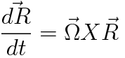
This also means that changing the laser frequency (pulsing)will make Ω and δ (detuning) depend on time.
Thursday, 05 July 2012
My search through the Phys. Rev. article's references has led me to the topic of Bessel beams. Rather than using an axicon lens (which is a bit pricey) or a spatial light modulator (also pricey) to create such a beam, one can use a tunable acoustic gradient index of refraction lens (TAG lens). It consists of a cylindrical cavity surrounded by a piezoelectric ring that produces an acoustic wave. The fluid that is within the lens changes its density and in turn its refractive index as an effect of this disturbance. From there the laser beam can create a Bessel beam pattern like it would with an axicon lens. The main difference, however, is that the TAG lens is tunable, therefore the number and size of the rings seen can be changed by adjusting the voltage and driving frequency.
Later in the day, Dr. Noe decided to talk to us about diffraction. He started with asking what we thought the word defined and how it differed from interference. In his mind, as well as ours, diffraction embodied Huygen's principle, where each point on a wave front is its own source of light. Interference, on the other hand, involved adding multiple wave fronts together, thus resulting in destructive and constructive wave forms. He then had Jon draw a diagram representing Huygen's principle, which was similar to what I drew for last semester's project. From there, it progressed into a discussion of slits of finite and infinitesimally small widths. Again, we drew graphs to portray the fringe patterns for two infinitesimally small slits, one finite slit, and two finite slits. We realized afterwards that the pattern for the latter situation is the combination of the first two graphs!
To add a little math into the equation we derived the intensity
distribution for two infinitesimally small slits. (I will write up these
equations in LaTex).
Wednesday, 04 July 2012
Today, my dad came for a tour of the lab. Immediately, he began asking questions about the equipment and various setups. I showed him the optical fiber set up and the Mach-Zehnder interferometer. As usual, he was curious to find out every setup's application and inner-workings. Melia also explained her interest in Bessel beams, and showed him the Airy pattern that she developed in the back room.
Surprisingly, my dad found the greatest enjoyment in the pig toy. Although he immediately knew there were two mirrors, he still wasn't sure on how the image of the pigs appeared. We gave him an introduction to real and virtual images using diagrams of lenses and mirrors, and though he shook his head in agreement, I'm not sure he fully understood the concepts.
Tuesday, 03 July 2012
The references of the Phys. Rev. article are leading me to more information on the interaction between acoustic waves and optical waves. I keep coming across "piezoelectricity" and "piezoelectric transducers" in my search and found out a little bit about the terms. Charge is able to accumulate on the surface of a material due to the presence of mechanical stress! So, a piezoelectric transducer is able to measure this stress (pressure, acceleration, vibration) and turn it into an electrical signal for measurement. Now, the question is "why get so interested in using acoustic waves to create an optical vortex?" According to what I've read, this method makes stable optical voritces with an orbital angular momentum (OAM) of +/- 1. We don't have the equipment here to setup something as intricate, but it's a topic that really sparks my interest!
Monday, 02 July 2012
I was looking through more articles when I found one related to acousto-optics. It involves using acoustic waves to transfer orbital momentum to an optical vortex. This acousto-optic interaction creates optical vortices over a variety of wavelengths! It sounds nice, but it isn't as simple as sending acoustic waves down an optical fiber. However, I am presently looking at the article's references to find something that may be doable in the LTC!
Friday, 29 June 2012
Today, Hal came to the LTC to give us an introduction lecture on quantum mechanics. Before actually diving into quantum theory, he started with deBroglie's hypothesis where λ= h/mv in order to connect it with the Schrodinger equation. He then said quantum is best introduced by starting with a classical standpoint involving an oscillator. After writing down the differential form of the oscillator's equation of motion, Hal pointed out that there were an infinite amount of solutions. This why in quantum, one is more concerned with finding an answer rather than knowing what that answer actually looks like! He then demonstrated this with both an uncoupled and coupled oscillator (two masses at the end of two pieces of string connected by a straw). This is where he began the discussion on "normal modes". He brought two relatively old, but effective, videos that portrayed these modes well. After watching the videos, he asked us a question about the coupled oscillator: When the two pendula are at the same amplitude, how does one pendulum know to continue transferring its energy in a specific direction?
Thursday, 28 June 2012
I didn't spend much time at LTC today because of the WISE orientation. I helped at the question and answer panel, and proceeded to help the two new physics students with their schedules. I encouraged them to take PHY 141 with Matthew Dawber, and I also invited them to take a tour of the LTC when they were finished. At first I lost Angela, but she managed to find the LTC on her own with no problem! We showed them the different setups, such as the optical fiber and interferometer, and, as usual, we showed them the pig toy. They seemed to be genuinely interested in physics, and I really hope they enjoyed the tour!
Wednesday, 27 June 2012
Our schedule for today was quite full! We had our regular meeting with Michal Simon at 12, where we again gave an update of our research developments. I explained the optical fiber setup that is in LTC, while Melia discussed her interest in Bessel beams and Jon discussed his desire to work with optical vortices. Immediately after the meeting, the whole REU program went to a graduate school panel. We were told what the most important credentials were for being accepted into a graduate program. For example, research experience and letters of recommendation are very influential in the evaluation process. After returning to the LTC, I started reading a book called The Complete Book of Holograms: How They Work and How to Make Them.
Our final meeting was with Marty, Hal, and John where we all discussed our topics of interest. Ariana told us about her pursuit in Moire patterns at her own dorm! She made lines of text on her computer and dragged the windows over each other to achieve this pattern; I was impressed that one could do something like that! I told Hal that I read up on the effect of acoustic waves on a light propagating through a fiber, which he told me was called Stimulated Brillouin Scattering (SBS). He said it was something that experimentalists want to avoid, but what if one can use it to one's advantage?
Marty then continued to help us with the optical fiber setup. Previously, we noticed fluctuations in the intensity of the new laser. To take a closer look, we hooked up the photodiode to an oscilloscope. We immediately noticed the voltage oscillating upwards and downwards as if it were "breathing". Jon and I thought maybe it was due to the fiber itself and replaced it with a new one, however, we were given a similar result. Is it the table's instability? Is it the air current in the room? Maybe there is stress on the fibers we can't determine by eye, since both fibers were wrapped up tightly.
Tuesday, 26 June 2012
I spent most of today reading a lecture on the introduction to quantum mechanics from the University of Cambridge. It starts out with a clear overview of basic mathematical concepts, such as complex exponentials, operators, and Bra-ket notation, then moves on to explain Hamiltonians and spin. I was excited that I understood what I was reading, and I'm no longer as afraid of the math as I used to be! I wrote most of what I learned in my research notebook.
Monday, 25 June 2012
Today Ariana Ray from the Simons Fellow arrived. She was given a quick tour of LTC and a notebook, after which I explained, along with Jon and Melia, the importance of taking notes. She now has a comfortable spot at a computer desk in the back!
Jon attempted to get the beam through the single-mode fiber before lunch time with no success, but afterwards he was able to get a nice bright spot on the wall! Marty helped us to compare the intensities of the incident and exiting beam using a photodiode, multimeter, and a 1kΩ resistor. There was over a fifty percent transmission, but we soon noticed an odd fluctuation on the multimeter. The intensity would peak at 262mV, then slowly decay to 244 mV and repeat. We decided to see if another laser acted similarly using the photodiode, but saw less of a jump in intensity. Since we came to the conclusion that the original laser we were using was old, we replaced it with the more stable one.
Friday, 22 June 2012
Today, I reviewed evanescent waves. These are standing waves that occur in the near-field and their intensities exponentially decay with increasing distance from their origin. How are they formed? The total internal reflection of sinusoidal waves optically disturb a second medium. This disturbance is in the form of an evanescent wave. I also looked up negative indices of refraction; the wave phase is in the opposite direction of the wave itself! This gives materials with negative indices the unique property to enhance evanescent waves which contain information at very small wavelengths. The equation n= c/v can be expressed as n= (εμ)^(1/2), where ε and μ are permittivity and permeability respectively. ε can be negative naturally, but μ cannot thus leading to the need to engineer artificial materials.
Thursday, 21 June 2012
I got to work with optical fibers today! The setup consisted of a HeNe laser, two mirrors, a coupler, and multi-mode/single-mode fiber. To start out, one must properly align the beam so that the heights of the beam relected off the first and second mirror are the same. I used a piece of cardboard to mark the heights and compare them. Also, the reflected beam entering through the coupler should be parallel to the edge of the setup's platform so that it doesn't veer off on an angle. The spot of light that is seen should be a uniform circle as well.
When I first tried getting light through the fiber, I used the "step and sweep method" where one moves one mirror a certain amount then scans with the other to find the maximum intensity. I had trouble doing this properly so Dr. Noe jumped in to help! He suggested to have the fiber loosely connected to the coupler, then use the "step and sweep method" to find the maximum intensity. Then, when the maximum is reached, push the fiber in a little further until it dims (still visible). You then repeat, where every time you reach a maximum you push the fiber in slightly more and continue the same procedure as before until it's fully connected to the coupler. When we finally finished, the beam exiting the fiber was seen on the wall. There was a pattern (like the speckle pattern) that formed where one sees the superposition of different modes! Pretty cool!
We then decided to switch to the single-mode fiber, which poses a greater challenge (yay!). Since we already found the maximum intensity for the multi-mode, we had a good starting place and decided to immediately connect the fiber fully to the coupler. After doing the same procedure as with the multi-mode, we got a decent sized spot (it wasn't very bright, so it probably wasn't the intensity maximum). It was a fun day today, and I'm glad I was able to do something hands-on!
Wednesday, 20 June 2012
Today, we had our first meeting with Michael Simon and the other REU fellows to discuss our current progress. Our LTC group explained our interests and ideas that developed from reading many articles and journals. Kate and Sarah, who are working with Michael, are making graphs that compare the solar masses at different times of young stars. June is ultimately assigned to fix a diode laser for Dominik and Yokov is working on programing for an electron beam for BNL's new collider. David is doing a theoretical simulation for water splitting (something that is way over my head).
Immediately after, our LTC group had a pizza lunch while Dominik explained ultra cold atoms. It was a very interesting and understandable presentation that explained, in simplest terms, the process of laser cooling and trapping. We then had a tour of his lab. The setup used for making Boson Einstein Condensates (BECs) was mindblowing and was said to take two years to organize.
Tuesday, 19 June 2012
I read several articles today on various topics. I added them to the "Links" section. "A New Way to Channel Light" and "Optical Fiber Pressure Sensor..." were the two that captured my interest the most. I really would like to incorporate optical fibers in my project somehow. Dr. Noe then reiterated how light becomes circularly polarized and emphasized the x and y components must be 90 degrees out of phase and equal to one another (otherwise it will be elliptically polarized). He also explained that shifting the frequency of light with an Acousto-optic Modulator (AOM) is used for laser cooling.
We then discussed "red eye" and the properties of Scotchlite 3M (reflectors). The phenomenon of "red eye" occurs when the lens of the eye reflects the light of a camera's flash back to the source. Moving the flash further away from the person will reduce red eye, since the light will spread over the distance. A past WISE student, Kristin Regan , did her project to explain this effect with a crystal ball. Similarly, the Scotchlite 3M has tiny glass balls (500 microns) on the surface, thus reflecting the light back to the source. There is a certain focal length at which one can avoid red eye/ the reflective glow.
Monday, 18 June 2012
Today was Bryce Gadway's thesis defense on "Matter-Wave Dynamics in Tailored Optical and Atomic Lattices". Everything was incomprehensible to me, but I could clearly see that he knew what he was talking about. After we left, he was bombarded with questions, and he was able to answer them fully and clearly. Back at LTC, Melia gave us a nice explanation/introduction to Fourier transforms and analysis. She took notes from a book called Who is Fourier? that gave an interesting (and understandable...yay!) interpretation of the mathematics. I'll definitely read it myself one day.
Friday, 15 June 2012
Today, I found Marty Cohen's patent for laser surgery on the computer. I was searching for information on optical fibers and I came across it. He decided to replace the final length of a fragile optical fiber (used for endoscopy) with a quartz/sapphire tip to prevent breakage within the human cavity. We also had a look at a framed "Contrast Enhancement Filter" (CP-70). It had the odd property of becoming blocked out when flipping the filter to the other side and looking at your reflection in a mirror. After Dr. Cohen pointed out the initials "CP", we realized that it was a circular polarizer. In order for circular polarization to occur, light must first be linearly polarized then go through a quarter wave( λ/4) plate. When the light is reflected back, it changes from right to left circularly polarized or vice versa depending on its initial circular polarization. The light can no longer go through the λ/4 plate which is specific to left or right cicularly polarized light, thus blocking out the light. If light goes through the quarter wave plate first, then there is no circular polarization. Question: How does one know if light is right or left circularly polarized?
Since the weather was nice and the sky was clear, we did some activities outside. Dr. Noe showed Jon and Melia sunlight through a small hole, the blurring of shadows, and reflected sunlight off a mirror. We had a fun time burning paper with a magnifying glass! He also gave us a pair of +1.25 reading glasses (convex) and asked us the significance of the number. Since the sunlight converged at a focal length, f, of 80 cm, +1.25 represents 1/f.
Thursday, 14 June 2012
This morning, at 11, Hal and Bruce Shore came to LTC to explain the significance of linear algebra in quantum mechanics. The complex vectors used in quantum are eaily organized into a column vectors, thus making it easier when multiplying it to the Hamiltonian. Bruce also expressed the importance of matrices in Euler's equation, where in eiX=cosX + isinX, X can be represented by a matrix rather then a complex number. Bruce then made it easy to visualize that the discrete energy states of an atom are proportional to the discrete quantum states, therefore if there is a large number of atoms in each state then there exists a probability that you'll find an atom in that state. Afterwards, we went Bruce Shore's final talk. Although I currently have a lack of understanding, I appreciate him for devoting his time to explaining and shining some light on the concepts of quantum.
Wednesday, 13 June 2012
There was another talk with Bruce Shore today that continued the topic on "visualizing quantum states" from yesterday. I decided to take time after to study some quantum mechanics. The math is surpirisingly undertstandable and I enjoy the concepts. I look forward to taking a formal class on the subject. Dr. Noe showed us a bookmark with lenticular lenses. The lenses give the image on the bookmark a 3-D aspect and depth, when in fact the lenses refract the light and magnify certain images at different angles.
Tuesday, 12 June 2012
Today is the first day of the REU program. I am working with two other college students, Jonathan and Melia. They received the same advice (and lab notebook) that I did on my first day at LTC. Dr. Noe also spoke about previous projects done on tenuative total reflection and did small demonstrations involving the pig toy and birenfrigence. Currently, I am thinking of a project I can take on for the rest of my time here. I have a possible ideas involving holographics, optical fibers, or structured light.
Thursday, 03 May 2012
Since I was required to do a final lab project for my PHY 142 class, Dr. Noe allowed my group and I to work in LTC. We decided to setup a Michelson interferometer experiment to calculate the wavelength of a HeNe laser. Before beginning the experiment, Dr. Noe showed us how a photodetector and an oscilloscope to measure the frequency of light. I then showed my group members how to properly align the mirrors and lense to obtain observable fringes, thus allowing the photodetector to detect the fringes and the counter to keep track of the fringes' frequency. To move the mirror on the stage, we used a 1 rpm motor with a custom attachment to turn the micrometer steadily (this device was made, but never used by, a previous student). We allowed the fringes to pass for 2, 4, and 8 minute intervals. At first we noticed slight jumps in the fringe counts and decided to tape the motor down to the table to prevent vibration. This, however, amplified the effect of the vibration and led to more miscounts. We also saw fringes within fringes and realized that the mirrors path lengths were differently. To fix this, we moved one mirror closer. We then calculated the path length for a certain time interval and divided it by the number of fringes to obtain the wavelength (our average wavelength is 630 nm).
Wednesday, 25 April 2012
Today was the URECA celebration. There were over 200 posters presented at this event, showing the ever expanding participation in undergraduate research. Fortunately, our table was near the entrance of the SAC Ballroom and attracted a lot of attention. Along with the poster, our table included several items for fun demonstrations such as the pig toy, a simulation of a solar eclipse, a giant kaleidoscope, and a retroreflector. I presented my poster to many people with varying interests and knowledge in optics and physics. I also saw my physics professor, Matthew Dawber, along with a physics classmate, Vyassa Baratham, who presented a poster as well. It was exciting to see the involvement and interest in the field of research, and I am looking forward (even more than before!) to conducting further research with Dr. Noé this summer.
Monday, 23 April 2012
We applied last minute changes to the poster before bringing it to the Social and Behavior Sciences building to be printed. We watched excitedly as our poster came to life as it was exiting the printer! We also had the file compressed into a pdf version (the file is now 220 KB!!!) for convenience.
Friday, 20 April 2012
I continued to edit my poster in the lab. The poster is finally taking shape, although there is still some tweeking and re-wording to be done. It's strange that this semester long project is coming to an end!
Wednesday, 18 April 2012
Today, I started brought my laptop to the lab so I can start creating the actual poster. I already organized the different sections of my poster according to certain topics. For example, the first column contains the background on angular size. Ben is also here working on his project.
Monday, 16 April 2012
We drew a layout for the URECA poster on the white board today. This helps us envision the organization for the actual poster. Dr. Noé will e-mail me a past poster so I can use it as a template for my own. I plan to bring my laptop to the next meeting to work on the poster.
Friday, 13 April 2012
Today we realized that the solar distance on 12 March (148.674 X 10^6 km) is actually less than the average value we used (150.0 X 10^6 km). We also used a more precise value of 2 X 696000 km for the solar diameter. The "new" α therefore is 9.36 mR. We added this to the Excel spreadsheet and noticed a slight shift in the six measured values. We used the method of least squares to see if this α produced a better fit which, in fact, it did!
Monday, 09 April 2012
We finished writing the abstract. Dr. Noe has sent a copy to Dr. Cohen to review. Next visit we will use the white board to organize the content of the poster board.
Monday, 26 March 2012
Today we began writing an outline for an abstract for URECA. We also must make a poster board for a presentation.
Friday, 23 March 2012
Dr. Noé suggested that I add a diagram of diffracting sunlight into the report to emphasize how students with some knowledge of optics can incorrectly explain why sunlight "spreads". When I first tried explaining the "spread" of light I drew a similar diagram where sun rays diffracted after passing through a small hole.
Monday, 19 March 2012
Today we made small adjustments to the webpage's organization and picture orientation. We also added "under construction" at the top of the page to warn people before viewing the report. We are getting closer to finishing this report!
Friday, 16 March 2012
Today we plotted the measurements that were recorded from last session and then made a prediction curve based off the known angular size of the sun. We assumed the curve follows a hyperbolic function since the diameter of the image (d) and the diameter of the hole (d_0) are the same at distance D = 0. We then added d_0 and α to the prediction and saw that it matched the data almost perfectly. This was a great surprise!
Monday, 12 March 2012
Today was an experimental day! I printed out a template that Dr. Noéand I created to use as a measuring tool. It has 6 concentric circles with diameters that range from 5 mm to 30 mm in 5 mm steps. We noticed that the diameters were off by a certain factor, but we still decided to take measurements using the template (we took the discrepancies into account when plotting the data). We originally had sunlight entering through a small hole and onto the measuring template, but the image was too dim to measure at greater distances. I thought that using a mirror would produce a image that is easier to see because it would not be obscured by direct sunlight. To stabilize the mirror, I attached the mirror to a stand that Dr. Noéprovided. I then taped a black sheet of paper with a 3.5 mm hole in it to the mirror's surface. I held the template in the path of the reflected sunlight and varied its distance until the image matched a circle on the template. Dr. Noémeasured the distance with measuring tape. We repeated this for every circle. Next time we'll plot the data!
Friday, 9 March 2012
We looked at Jahnavi Sajip's report today. In 2008 she and Dr. Noe made a measuring tool or "circular ruler" to measure the radius of a laser beam's "dot". We thought this would be useful for measuring the diameter of a circular image in our experiment so we modified the template in xfig.
Tuesday, 6 March 2012
Recently I have been reading about acousto-optics and holography. These branches of optics are really interesting [and complicated!!!!] and I will continue to look for more articles and books on these topics.
Friday, 2 March 2012
Today Dr. Noé and I organized and edited my report at LTC. Dr. Noe is currently uploading photos from his camera that I need to add to the report. I also drew a diagram of what an observer would see in the 3 sections (umbra, penumbra, antumbra) of an eclipse. This will be added into the report as well.
Monday, 27 February 2012
We recently found out that there is another part of an eclipse called the antumbra. I redrew the diagram in my notebook to include this section. Dr. Noé learned about the antumbra while meeting with a high school student at the LTC, while I happened across a diagram on Google that pointed it out. We were both surprised and excited to learn something new about total and partial shadows! It’s also a funny coincidence that we found this out around the same time as one another.
Friday, 24 February 2012
I have started to create a list of titles for my report. Choosing words related to the report’s subject helps to spark a clever idea for a title. Creating the right title takes time, so I try to avoid putting random words together and switching them around. So far I like the title, “The Geometry of Sunlight”.
Monday, 20 February 2012
Today was the last official day of my first WSE187 rotation, but I have decided to continue to work with Dr. Noé for the remainder of the semester.
Friday, 17 February 2012
Today, I created a password for the SSH system so I can connect to the LTC network from any computer to view and edit my files. I am still unfamiliar with Linux; therefore I will need to practice using it elsewhere. Dr. Noe and I then decided on an experiment where we can observe and record the sun’s movement in the ecliptic plane. A sheet of black paper with a hole in it was taped to a window to allow sunlight to pass through the hole and onto a screen several meters away. I traced the circle of light that appeared on the screen and continued to do so every 2 minutes. The circle of light approximately moved its own diameter in those 2 minutes. It seems that both the sun and time move quickly! We finished the day by having a little fun with a magnifying lens and that same sheet of black paper. The sunlight that passed through the lens converged at the lens’ focal length with devastating results! Sunlight provides an irradiance of 1kiloWatts (kW) per square meter at the earth’s surface. Now let’s imagine it converging to a spot of about 4 millimeters in diameter: that’s about 450kW per square meter! I know what I’m doing when I get home…
Monday, 13 February 2012
First, we edited my journal entry from the previous meeting. Dr. Noe corrected my terminology for angular diameter and helped strengthen my explanations of the indoor and outdoor experiments. In the same document, we started an outline on my final report for WSE 187 that provided a logical structure of events. This will help me organize the content of my final report. To end the day, we were curious if there is an observable dividing line between the umbra and the penumbra in a solar eclipse. We used a coin to project a shadow onto a piece of paper to produce a similar event, but the dividing line between the penumbra and umbra was too difficult to observe. We then decided to switch our experiment to reflecting sunlight off a small mirror with an irregular outline on to a paper with a circle of known diameter so the reflected sunlight was easier to measure. The design of the mirror was simple; we covered a pocket mirror with a black sheet that had small irregular holes cut out from it. We wanted to see when the reflected image no longer "looked like" the irregular shape, but instead was seen as a perfect circle. Next time we can take precise measurements and use a tripod to keep the mirror steady!
Friday, 10 February 2012
Today Dr. Noe and I continued our previous discussions about shadows, and about sunlight passed through a small hole or reflected off a small mirror. The night before, I had e-mailed him thinking diffraction explained our observations in these situations. When we met he helped me to see that no more than simple geometry is involved, by asking me to draw a diagram of sunlight entering a small hole and hitting a screen. As I drew this picture, I realized excitedly that although there is diffraction, geometry is the dominant factor.
As the screen gets further from the light source the angle at which the light hits the hole causes the light to “spread”. Using the estimate that the sun's angular diameter is 1/100 radian from our earlier outside experiment, we calculated an experimental diameter of the sun (1.5E 6 km) which was surprisingly close to the sun’s actual diameter (1.39E 6 km) by multiplying the angular diameter and the sun's distance from the earth. Fun fact: The moon also has the same angular diameter as the sun, thus explaining why the moon perfectly “covers” the sun in a solar eclipse. It’s amazing what you can do with geometry! We even calculated that it takes 2 minutes for the sun to fully set after it reaches the horizon.
We ended our meeting by observing the spreading of light when a laser beam is passed through a very small pinhole. On a piece of paper 300 cm away we observed a spot of light 1.5 cm in diameter surrounded by a series of faint rings. From the small angle approximation the angular size of this spot is thus 1.5/300 = 5.0 milliradians (mR). This is about half the angular spread of sunlight, 1/100 radian or 10 mR.
Dr. Noe explained that angular spread due to diffraction is approximately given by λ/d, where λ is the wavelength of the light and d is the diameter of the pinhole. In this case the wavelength of the laser is about 600 nano-meters and the pinhole diameter is 200 micro-meters, so the estimated angle of diffraction is 3.0 mR, in rough agreement with the observed angle 5 mR. We can conclude that, unlike our earlier experiments with sunlight, in this case diffraction plays the dominant role because the pinhole is so much smaller. The moral of this story: quantitative results are the deciding factor in an experiment.
Monday, 6 February 2012
Today, Dr. Noe first showed me the inner workings of the LTC website. We talked about basic HTML and the Secure Shell system (SSH) that is used to connect securely to the website. We then moved on to working with a Michelson interferometer setup that had been put together by Gaby last summer. Dr. Noe explained that the laser beam’s intensity follows a Gaussian curve [http://www.thorlabs.de/images/TabImages/BeamDist_sm.gif]. Also, the laser beam’s increase in width with increasing distance is not linear but rather hyperbolic. At the laser the width has a minimum value, w0, known as the beam waist [http://laser.physics.sunysb.edu/~wise/wise187/2005/reports/deb/sketch2.gif]. Dr. Noe told me how to adjust the mirrors and beam splitter to overlap the two beams and emphasized that they should not diverge by more than about one mm per meter. After doing this I was happy to see fringes displayed on the wall and noticed that any slight disturbance of the mirrors caused the fringes to shift drastically.
Dr. Noe and I ended our meeting by going outside to watch the senior astronomy students experiment with an astronomical radio wave interferometer; the students were attempting to measure the size of the Sun. While we were outside, Dr. Noe asked me why an object’s shadow blurred as the object’s height off the ground increased. He also pulled out a mirror and reflected the sun's light onto a wall. As the mirror’s distance from the wall increased, the spot of reflected light on the wall got larger. He asked me why, and then that’s when I went into deep thought mode ...
Friday, 3 February 2012
Today's meeting started with my showing Dr. Noe the extensive notes I took while reading an optics textbook [Introduction to Optics, by Predrotti and Pedrotti] on my own last semester. After looking over my notes, Dr. Noe suggested I take notes differently to avoid overwhelming myself with too much information. From now on I will try to focus on one idea or topic at a time to prevent this. Dr. Noe and I then read through my biography and first few journal entries together, and we discussed ways to improve the style, clarity and accuracy of my writing. For example, the interferometer mentioned in my January 30th entry is not a Michelson Interferometer but a novel interferometer (similar to a "Sagnac" type) put together by two previous LTC students. I also didn't explain how a rubber band can "manipulate the fringes."
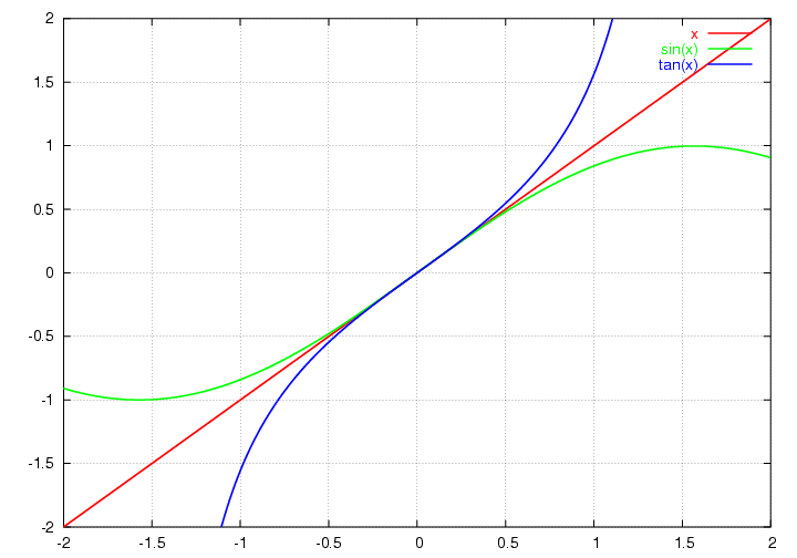
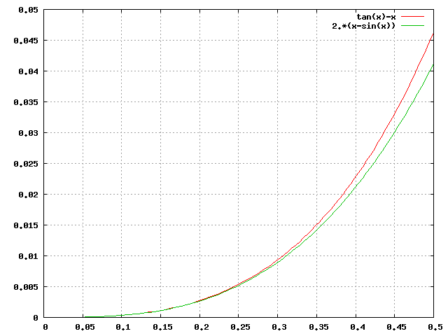
Next, Dr. Noe showed me the kissplot that he once made to illustrate the small angle approximations for sin(x) and tan(x), that we discussed in our previous meeting. The name "kissplot" refers to the idea that two curves are said to osculate or "kiss" if their values, and first and second derivatives, are equal at some point, as described here. Dr. Noe explained that the kissplot is not the best example of kissing curves, since the curves involved have zero curvature (R = ∞) where they meet. A better example is a circle and a parabola, constructed to most closely match at the origin. We concluded our discussion of the small angle approximation by reviewing the infinite series expansions for sin(x) and cos(x), and deriving the first two terms of the series for tan(x). As shown in this plot, tan(x) is about twice as far above the line y=x as sin(x) is below it, for small x.
Finally, Dr. Noe took my picture to put the final touches on my LTC profile. In the picture I'm posing with a rubber band and a mirror to illustrate the nanomover idea; if you look carefully you can see his reflection in the mirror. It’s a pretty cool yet creepy picture!
Monday, 30 Jan 2012
We began our discussion on the Michelson Interferometer and the use of rubber bands to manipulate the fringes. Dr. Noe mentioned that this was a relatively new method of looking at it and said it’s something I could work on for a project. He suggests using a spring scale or even the elasticity of the rubber band to measure the force applied and then we’ll observe if it obeys Hooke’s Law. On another note, we began talking about exoplanets since I came back with notes about “the closest star”. We can examine these exoplanets through “detectable changes” such as the Doppler Shift and the transit method. I was also reminded that astronomers use arcseconds as an angular measurement. I was made aware that two nights ago was in between (but positioned closer more westwardly) Jupiter and Venus. Last night the moon “dropped back” and was closer to Jupiter yet still in between, and tonight the moon will be behind both Jupiter and Venus. I’ll be looking at the s sky tonight! In addition, we spoke about the ecliptic plane to explain the path of the moon and the sun in the sky and that the planets move relative to the stars therefore explaining the origin of their names, “wanderers”. The discussion of the moon also led to a conversation about tides and so I’ve taken the liberty of printing out a tide table of Montauk Point for January 2012. We also jumped to an in-depth discussion about parsecs , optical tweezers, and dimensional analysis. As a result of our heated discussion of dimensional analysis, we went over the fundamentals of radians, which I thought was more fun than it should have been!
Friday, 27 Jan 2012
This is the first day at the Laser Teaching Center, the first of my WISE 187 rotations. Truthfully I am very nervous and intimidated about the equipment I see around me. Dr. Noe has given me a notebook to keep track of what he is telling me and to record what happens in the lab. We had several discussions today about past and ongoing projects of students, one of which was the Michelson Interferometer. Dr. Noe explained the process and results of the interferometer, and I drew diagram of it in my notebook. We also went over internal reflection, aether or better yet the lack of aether that light travels through. I was questioned about a 9V battery, an everyday object, to which I found out I knew little about. I was also asked to answer the question ‘how far away is the closest star?’ I did not know the answer at the time, but I have proudly found out it is 4.27 light years away! There are a lot of things I do not know, and I’m excited to learn more.