Report
|
Spatial Filtering in Optical Image ProcessingLidiya Mishchenko Dr. John Noe Dr. Harold Metcalf Laser Teaching Center Stony Brook University
| Abstract: Abbe's theory of image formation states that objects illuminated by a plane wave form diffraction patterns in the back focal plane (or the Fourier plane) of an objective lens. A faithful image of the object can only be formed (with the help of a second lens) when all the diffracted orders are allowed to pass through the objective lens. The purpose of the project was to observe how different spatial frequencies of the aforementioned diffraction pattern contribute to image formation. High-pass filters involve obstructing lower spatial frequencies located in the middle of the object's diffraction pattern in the Fourier plane. This kind of filtering results in edge enhancement of an object. Edge enhancement can be used to easily locate and define the edges of fine objects. Low-pass filters block out higher spatial frequencies located at the edges of the diffraction pattern in the Fourier plane. Blocking out higher spatial frequencies leads to degradation of the image quality. All lenses are of finite size, so all image formation involves low-pass filtering to some degree, and all lenses contribute to image degradation of the original object. Low-pass spatial filtering can be used to filter out grain noise highlighted by higher spatial frequencies in photographic emulsions. Using various high-pass and low-pass spatial filters, processed images of objects were taken and analyzed using a CCD camera. The experimental results clearly supported Abbe's theory of image formation. Low-pass spatial filtering of an image of a Ronchi grating (with an iris acting as a filter) showed expected image blurring. High-pass filtering of an edge of an object (with circular obstructions in the middle of a transparent material acting as filters) showed edge enhancement, also as predicted. This experiment effectively illustrated that low spatial frequencies are important in forming the basic layout of an image, while higher spatial frequencies form the finer details, precisely defining the edges of the object. Amplitude spatial filtering is closely related to the more general field of Fourier optics, as well as optical imaging. The concepts of amplitude filtering, combined with those of phase filters, lead to the development of complex holographic optical filter systems, which have applications in pattern recognition and intricate data processing. This work was supported by a grant from the National Science Foundation (Phy-0243935). Introduction: Abbe's theory of image formation speculates that diffraction is an intermediate step of the process (see below source: http://www.doitpoms.ac.uk/tlplib/DD1-6/image.php). But what is diffraction? Diffraction is most simply defined as the bending of light around obstacles, or more accurately, diffraction is the Fourier transform of an image.
 Mathematically, Fourier theory asserts that all functions can be expressed in terms of sine and cosine functions with different amplitudes and frequencies. The Fourier transform of a function is like a continuous frequency spectrum of a signal, where each frequency's importance is weighed by their respective amplitudes. Squaring a Fourier transform gives an intensity distribution. Thus, a squared Fourier transform gives the intensity distribution of an image's diffraction pattern because, as you will see later, a diffraction pattern divides an optical signal into spatial frequencies and "weighs" their importance with an intensity distribution. When collimated light illuminates an object (consider a Ronchi grating for simplicity), light passes through the transparent portions of the grating undiffracted. The edges of the grating bend the light at certain angles to form a diffraction pattern (without a lens). The center of the diffraction pattern contains unbent collimated light. Light that is bent, forms maxima located at certain distanced away from the middle maximum. These maxima are diffraction orders. A lens "focuses" this diffraction pattern at its focus (Fourier plane). Actually, the unbent light that passes through the grating is focused at the focus of the lens because it is collimated light. The bent light comes to the lens at an angle, and thus the lens helps bend it even further away from the undiffracted light maximum focused in the middle of the pattern. So this is how diffraction maxima are formed at the focal plane of the lens. The lens simply "maps" and enhances how much the light diffracts around the object (it sorts the light into diffraction orders at its focus). In mathematical terms, in the Fourier plane, the optical information of an object is divided into frequencies. This is most easily seen with a pattern from a diffraction grating. (See below)
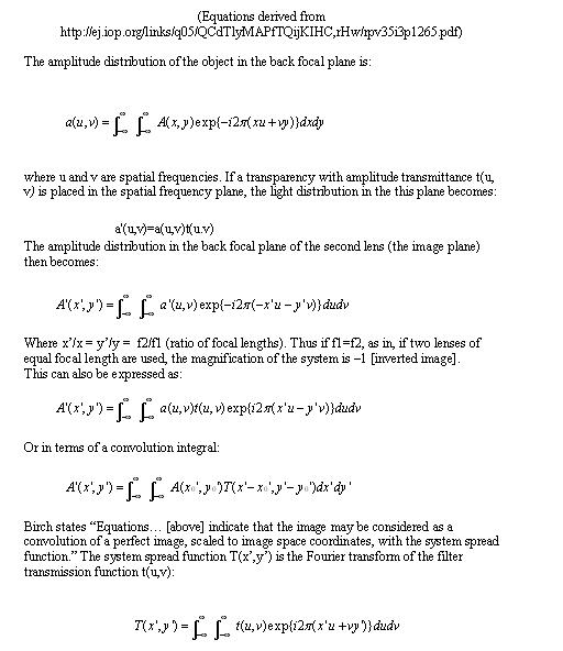
 This pattern is formed perpendicular to the slits of the grating. As previously stated, the middle maximum represents the light that passed straight through the grating. The further out the maxima, the more the light had to bend around the grating's edges in order to concentrate intensities at those spots. The middle maximum is called the zero order, and first side maxima are called first order, and so on. High spatial frequencies in Fourier mathematics correspond to high diffraction orders in diffraction patterns. Thus, for all objects, the frequencies located at the edges of the intensity pattern in the Fourier plane correspond to higher spatial frequencies. The lower spatial frequencies (for which the light did not bend as much) are located in the middle of the Fourier plane. A lens is usually used to create a pattern called Fraunhofer diffraction in its focal plane. (This is why a lens is sometimes referred to as a Fourier transform.) The back focal plane of the lens will then become the Fourier plane of the setup, and this is where the diffraction pattern or the Fourier transform of the object is located. Thus, in most cases, after the light passes the focus of this lens and its diffraction pattern is formed at the focus, it begins to again interfere to reform the image of the object. Theoretically, however, the image is never truly focused if the object is located a focal length away from the lens, so a second lens is needed to bring what would be an infinite image distance to a particular, finite image plane. (In other words, a second lens located a focal length away from the Fourier plane makes the infinitely far away image focus on the image plane.) In the experimental setup, then, a second lens is located a third focal length away from the Fourier plane and performs an inverse Fourier transform on the diffraction pattern, forming an inverted image of the object in its back focal plane. (See picture of 4f Setup, source: http://www.iop.org/EJ/abstract/0034-4885/35/3/305) The 4f setup makes locating the exact position of the Fourier plane and the image plane simple (everything is one focus apart). If the lenses are identical, then the image magnification is -1 (the image is simply inverted).
 Logically, one can now grasp that lower spatial frequencies (in the middle of the Fourier plane; the central maxima of the diffraction pattern) are responsible for producing the general outline of the image while higher spatial frequencies (in the periphery of the diffraction pattern in the Fourier plane) develop the high detail of an image, especially the sharp edges of the object. Using spatial filters in the Fourier plane, it is possible to observe the effects of both of these kinds of frequencies in a 4f experimental setup, as explained. Look at the low pass filtering of the letter B and the high pass filtering of an edge below.
  Theory:
Cleaning Up the Beam:
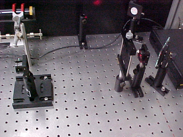
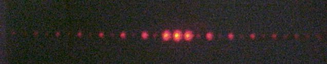
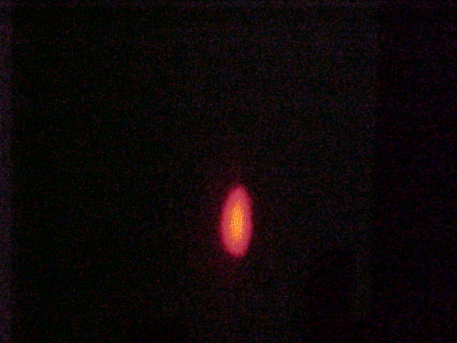
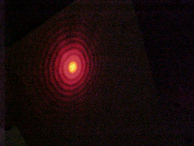 A second lens of a longer focal length is placed its focal length away from the aperture. This lens helps to expand the diameter of the diffraction pattern, and to collimate the beam. An iris screwed onto the second lens can be used to get rid of the outer rings of the pattern, resulting in a clean, nearly Gaussian beam of light. Compare the unfiltered and the filtered beams below:
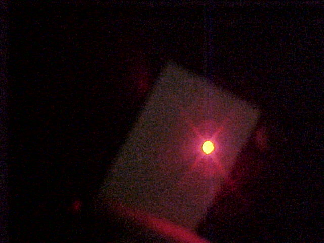  (The beam was polarized before entering the filter to lessen its intensity and not super-saturate the CCD camera.)
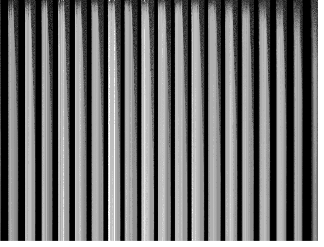
Low-pass filtering:
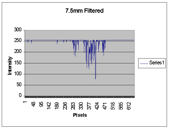
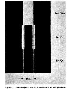
 Below is the image of the grating without any filter, and the image of the most filtered beam. Notice how much blurrier the latter image looks. One can still observe the general pattern of the object, but the lack of high spatial frequencies dulls the details of the image.
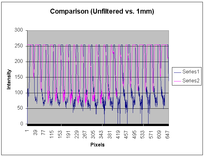
  Here is a graph comparing the unfiltered and filtered images. Notice how the minima of the filtered image (pink/Series 2) are blurred and not as clearly defined.
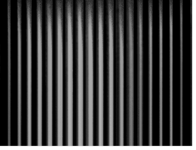
High-pass filtering:
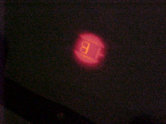
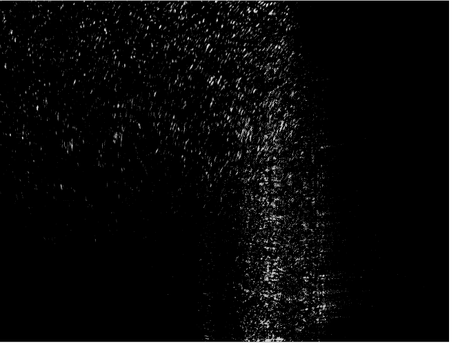
 A CCD camera was again used to record the images. Notice how, in the picture below, it is quite clear where the edge of the object is located. The graph shows the location very precisely.
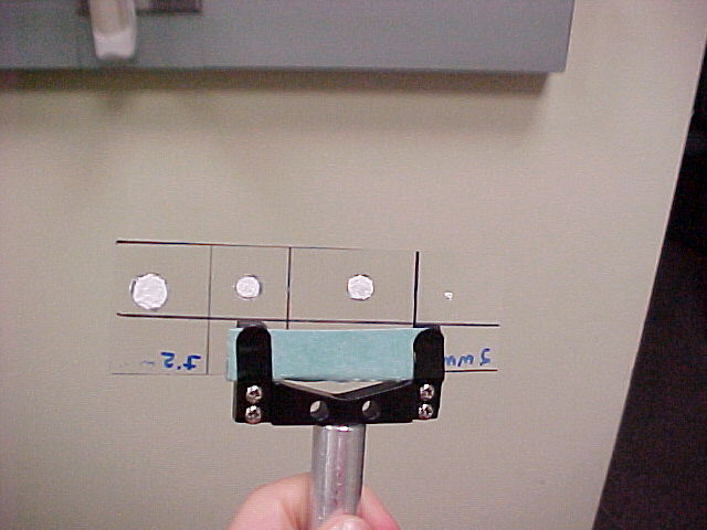
Mathematically, the transmission function of the high pass filter ends up being the subtraction of 2 sinc functions (because in reality this is band pass filtering and the lens limits the transmission of high spatial filtering). With this transmission function, the final intensity function of the image ends up highlighting the edges of the objects, with a noticeable minimum in between the highlighting maxima (see below, source: http://www.iop.org/EJ/abstract/0034-4885/35/3/305). The greater the number of higher frequencies allowed through, and the greater the number of lower frequencies filtered out, the sharper these maxima and minima become.(N is b/a where a is the diameter of the central obstruction in the filter, and b is the outer limiting diameter of the filter, which limits the number of higher frequencies transmitted.)
Orientation filtering:
  Sources of Error: Firstly, there are inherent errors in optical edge enhancement, especially of small objects, such as mutual interference of edges. There were some sources of error present in the setup addressed here as well. There was a lot of grain noise in the images from the CCD camera. This made it difficult to view edge enhancement. Also, the transparency used in high-pass filtering as part of the filter had a certain refractive index, which slightly changed the phase of the light. Thus, the high-pass filter was not purely an amplitude filter. Conclusion: The data makes it clear that high spatial frequencies form the edges of the image of an object, and the low spatial frequencies form the general outline of the object. Many applications exist for both kinds of filtering. Low spatial filtering can be used to filter out grain noise out of photographs caused by high spatial frequencies. High spatial filtering is useful when measuring the profile of an object or optically observing irregularities in the contour. Also, amplitude filtering performed here can be combined with phase filters in complex filtering. This kind of filtering can lead to pattern recognition and incorporates the ideas of holographic optical processing. Acknowledgements: I would like to thank Dr. Noe, Professor Metcalf, and everyone else who has helped me put this project together. References: Birch, K.G. "A spatial frequency filter to remove zero frequency." Journal of Modern Optics. 15 (1968): 113-127. Birch, K.G. "Spatial filtering in optical data-processing." Rep. Prog. Phys. 35 (1972): 1265-1314. Bonczak, Bazyli and Jan Dabrowski . "A school experiment to confirm Abbe's theory." Phys. Educ. 15 (1980): 235-237. Goldwasser, Sam. "Introduction to Fourier Optics." Laser Instruments and Applications. 1994-2004. < http://www.repairfaq.org/sam/laserlia.htm#liafop0 >. July 2004. "Image Formation." Diffraction and Imaging. July 2004. < http://www.doitpoms.ac.uk/tlplib/DD1-6/image.php >. Steward, E. G. Fourier Optics: an Introduction. New York: Ellis Harwood Limited, 1983.
|