Understanding Elliptically Polarized Light
Kristine Horvat and John Noé
Laser Teaching Center
Department of Physics & Astronomy
Stony Brook University
Introduction
This project was motivated by an interest in polymers and the many connections between polymers and optics, and specifically polarized light. Polymer materials consist of long chain molecules, which are often arranged in some specific way, such as parallel to each other. These specific molecular arrangements create birefringence, an effect in which the material's refractive index can vary with its orientation with respect to incident polarized light. It follows that birefringent materials can alter the polarization of transmitted light, creating elliptical or circular light from linear polarized light for example.
EP light can be created in other ways as well. For example, total internal reflection (TIR) creates a phase shift between components of incident linearly polarized light which are parallel or perpendicular to the plane of reflection, respectively. A device called a Fresnel rhomb uses this idea with two reflections to create a 90° phase shift, and hence circularly polarized light.
We decided to create a "half Fresnel rhomb" out of an ordinary 45-45-90 prism. Two such devices in series could give the same result as the much more expensive commerical Fresnel rhomb (Thorlabs $360). This turned out to be a good way to learn about EP light. We studied the EP light produced in the prism by measuring the transmission through a rotating analyzer Polaroid. The results were plotted in polar coordinates and compared with predictions. The prediction depends on the index of refraction of the glass in the prism, so we learned how to measure this by the critical angle method.
Two different prisms were used during this experiment. Results for the first prism(4.7 x 3.1 x 2.2 cm) did not agree with our expectations. We believe that this descrepencey is due to higher stress birefringence. The second prism(1.9 x 2.7 x 1.9 cm) was much smaller than the first and had an antireflecting coating on it. In general, we decided that for this kind of experiment smaller prisms are better.
What is Elliptically Polarized Light?
Light is "polarized" when the E-field vector of the transverse EM wave moves in a specific pattern that repeats with the frequency of the light. (Since this frequency is extremely high, only the recurring pattern is detectable, not the individual oscillations.) The most general pattern is an ellipse, and this form of light is said to be elliptically polarized. Special cases of elliptical light are circular polarized light and linear polarized light, which is the most common and familiar form. The polarization ellipse can be descibed by the phase difference between x and y components, which is 0 degrees for linear light and 90 degrees for circular.

Measuring Index of Refraction
The index of refraction was a very necessary quantity for us to define. First, we had to determine the critical angle. The critical agle is the angle at which the total internal reflection occurs. In a prism, one can tell that the critical angle has been reached if light is beginning to escape the far corner of the prism. After finding out the critical angle of the prism using basic trig functions, we were able to use a guess and check method using Snell's Law(nsin(theta)=nsin(theta)) to figure out the index of refraction of the glass. In this prism's case, the index of refraction was n=1.515.
This is what the critical angle of a laser through a prism looks like. Light just starts to escape the far corner of the prism at the critical angle.
Theory
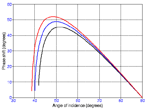
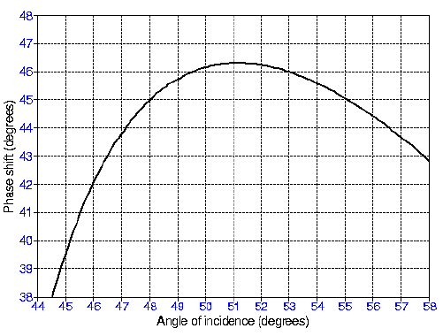
The first diagram is a graph of phase shift versus the critical angle for n=1.6, 1.55, and 1.5 respectively. The second is of a close up shot of the same graph but for n=1.515, which is the calculated index of refraction for our glass prism. Note that one can obtain a phase shift of 45 degrees at either 48 or 55 degrees.
Setup and Procedures
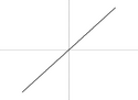
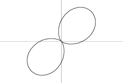
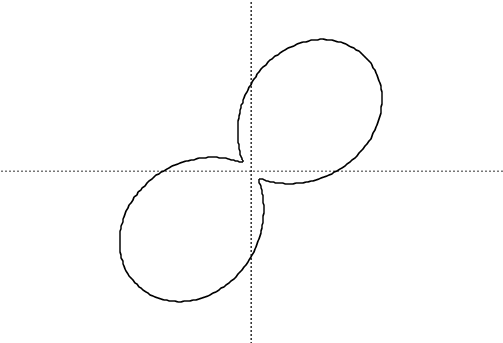
Since the HeNe laser used in the experiment was already linearly polerized, to get reading for linear polarized light, one must place a polarizer in front of the laser light and take intensity readings. When graphed on a regular x y plot, the graph is of a cos^2(x) graph, but when graphed on a polar plot, it looks like a sideways eight.
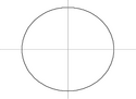
Circularly polarized light can be made by using the linearly polarized laser and shining it through two prisms, both angled at 54 degrees, and a polarizer. On a x y plot, the data looks like a flat line, and on a polar plot, it looks like a circle.
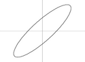
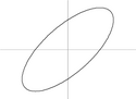
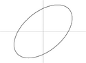
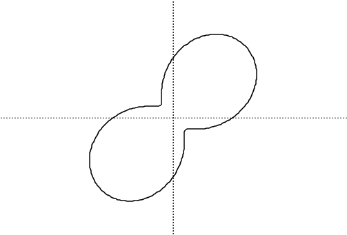
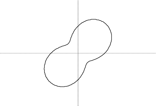
For elliptical polarized light, the relative phase and amplitude are not the same. Also, elliptical light can either be left or right handed. When graphed on a regular x y plot, the intensity of light through a polarizer versus the angle of the polarizer resembles a sinusoidal curve, but when graphed on a polar plot, it creates a 'peanut' shaped graph.

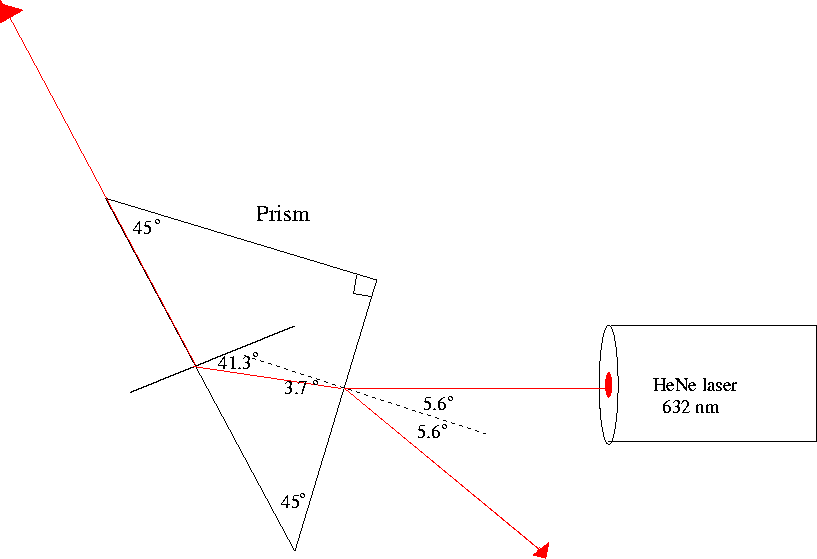
This is a diagram for the setup for creating elliptical polarized light.
Results

This is a 'peanut plot' for elliptical polarized light at 45 degrees incident.
We started by studying how elliptically polarized light can be created, described, and analyzed. We set up a simple computer model in a spreadsheet program to aid in visualizing elliptically polarized light and to show how it can be analyzed by passage through a rotatable linear polarizer. The formulae used were derived using the Jones matrix theory of polarized light, and the results were plotted in polar coordinates. The model was tested by creating a specific form of elliptically polarized light (45 degree phase shift), analyzing this with the rotating polarizer, and comparing the result to the prediction. The controlled phase shift was created by total internal reflection (TIR) at an angle of incidence near 54 degrees, within an inexpensive ($10) 45-45-90 glass prism. (Two such prisms can replace a Fresnel rhomb, a specialized and expensive optical element for creating circular polarized light.) As shown in the Figure, our measurement (data points) is in excellent agreement with the calculated prediction (solid line).
| Prism | Entrance Angle | Angle of Incidence | Method | Phase Shift | Predicted Phase Shift |
|---|---|---|---|---|---|
| 1 | 14 degrees | 54 degrees | full curve | 49 degrees | 45.5 degrees |
| 1 | 14 degrees | 54 degrees | full curve | 47 degree | 45.5 degrees |
| 2 | 0 degrees | 45 degrees | full curve | 40 degrees | 39.5 degrees |
| 2 | 0 degrees | 45 degrees | two point | 40 degrees | 39.5 degrees |
The next phase of the project will utilize similar measurements and analysis to characterize the optical retardance (phase shift) of various polymeric thin films.