Journal
December 14, 2010
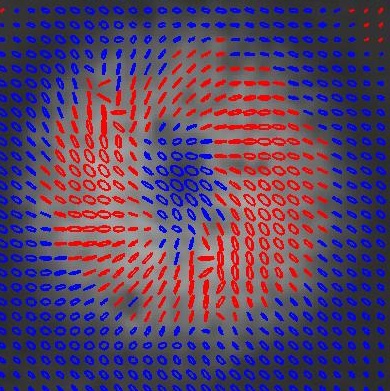
It is now several months after the end of the SBU REU program, and I figured that I would update on everything that's happened since then.On August 6th I gave my presentation at the REU symposium along with the rest of the summer research fellows. We said our goodbyes, though I knew that I'd be seeing some of them again at the Symposium on Undergraduate Research in Rochester in October. I had to leave Stony Brook that evening because my family was going to leave to go to the shore for the week before I returned to school. On the train from NYC to Philadelphia I started thinking about the project again because the polarization maps which I made (and which I had shown in my presentation) didn't really make intuitive sense. The central area should correspond to zero stress and thus zero birefringence, so the transmitted light should not have its polarization altered. Thus the light at the center point should be linearly polarized if the incident light is linearly polarized.
|
As is plainly evident, the central region exhibits circular polarization. There wasn't really a great explanation I could think of for this phenomenon, and it got me thinking that I had measured the Stokes parameters incorrectly. I stewed over this question for a while during my vacation in Avalon, NJ - internet searches did not reveal any paper that specified an exact procedure for measuring the Stokes parameters. The problem was eventually resolved by exchanging emails with Giovanni: we figured out that I had used an additional quarter wave plate in measuring the RHC and LHC intensities so that LP light was being represented as CP light. I had already recorded a great deal of data (varying stress, input polarization) using the incorrect procedure, and none of it could be used in my presentation for Rochester. The following day I took the bus from Atlantic city to NYC, then took the train to Stony Brook. Re-taking all of the data I wanted using the correct procedure took about 3 hours, and I then drove back down to New Jersey and arrived around midnight. The images below now represent the correct procedure and show horizontal linear polarization at the center, as expected.
The weekend of October 23rd I went to Rochester to perform with the Cornell Glee club, and I stayed the remainder of the weekend attending the OSA DLS conference. I attended two of the plenary talks, and one of them was a very interesting discussion of single molecule manipulation using optical tweezers by Steve Block from Stanford. He began by showing how the extremely high resolution of his technique could resolve the position of RNA polymerase as it transcribed a single base pair at a time and thus resolve the question of whether the enzyme proceeded in a continuous fashion or in short bursts. He then went on to show that by attaching RNA to a bead which was manipulated with tweezers he could probe the energy vs extension landscape of the molecule and in doing so infer when conformational changes were taking place. He mentioned that the nucleic acid folding problem is a simplified version of the protein folding problem, one of the biggest questions in modern biology.
August 3, 2010
To get a better idea of what the polarization structure coming out of the stress optic actually looks like, I recalled the polarization profiles presented by Giovanni in his talk. They were images with an array of polarization ellipses superimposed on the beam intensity profile. Such an image of my beam would be useful to have because it would provide quantitative spatial resolution of the polarization structure. These images are made by measuring the Stokes parameters and extracting the parameters for the polarization ellipse.The Stokes parameters are an alternative means of specifying the polarization state of light. They consist of four numbers representing the projection of the overall intensity onto various basis vectors. This is similar to the Jones vector formalism in that it has 4 parameters - a Jones vector is 2-D, but its entries are complex, so they require four numbers as well. The difference is that Jones vectors specify a phase but describe only fully polarized light, whereas Stokes vectors do not specify a phase but can describe partially polarized light. Also, as the Stokes parameters are a measure of intensity, all Stokes vector entries are real. The set of arithmetic operations associated with Stokes vectors is known as Mueller calculus.
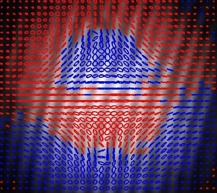
From the four Stokes parameters we may extract the parameters of the polarization ellipse: major & minor axes, orientation, and sense of rotation (also 4 parameters). The Stokes parameters (I, Q, U, V) are easily measured because they are sums and differences of irradiance measurements, which are easy to perform.
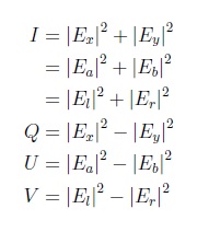
The first parameter I is the total irradiance. The rest of the parameters are differences in irradiance between two orthogonal analyzers using three different basis sets: x-y (0o,90o), a-b, which is rotated 45o to x-y (-45o,45o), and LHC-RHC. We can interpret these measurements by saying that V is the intensity of circularly polarized light and
is the intensity of linearly polarized light. Then the total intensity of polarized light is then:
This value can be less than the total intensity, reinforcing the fact that Stokes vectors can represent partially polarized light. The parameters of the polarization ellipse can be extracted using:
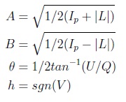
MATLAB makes it very easy to manipulate whole arrays of these parameters at a time to compute arrays of ellipse parameters. These parameters can be used to assign polarization ellipses on a pixel by pixel basis. I averaged these parameters over a small area and plotted the representative polarization ellipse for each small area.
|
In the above, it can clearly be seen that there are alternating left and right handed rings of circular polarization. At the boundaries, the circular polarizations superimpose to produce linear polarization, which corresponds to areas of half-wave retardance. At that radius, a counterrotating polarization pattern can be clearly observed.
July 28, 2010
Just did an experiment which, to me, seemed pretty cool. I have the circular polarizer and circular analyzer setup, and I removed the stress optic, replacing it with some of the transparency film I used to make the discrete wave plates. If you angle/bend the material just right you can get full half-wave retardance across the spot size, and the transmission through the analyzer goes to zero. This seems so counter-intuitive: how could adding transparency film which is transparent cause transmission to go to zero? It is of course due to the fact that linearly polarized light has not just a vector nature, but also a phase. To me, this seems just as significant as the experiment in which you add a 45o polarizer between crossed polarizers and observe transmission when there was none before. In that case, you add a partially opaque material to a system with 0 transmission and all of a sudden get transmission. In this case, adding a transparent material to a system with some transmission extinguishes the transmission. The conclusion is that light behaves in counter-intuitive ways when we consider that it has both vector and phase (polarization) properties. When these properties get mixed together, as in LG beams, the situation must get very complex indeed!July 27, 2010
I spent a lot of time today trying to find a text that could explain conoscopic interference. A paper that Giovanni pointed me to pretty much exactly demonstrates the pattern from the Pringles lid, so it seems like this is indeed what's going on. He also said that the pattern coming from the stress optic is also conoscopic interference, arising from the divergence of the laser that I'm using. Using a lens to get the beam significantly more collimated, the pattern doesn't change at all, suggesting that the effect does not come from divergence. It is turning out to be very hard to find a reference on this topic, as it is largely used in gemology, which is more of a practical art than a science.
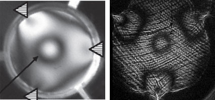
Stress optic between circular polarizers from Spilman & Brown (left) and my results (right). The plexiglass optic exhibits more fringes around the screws both because it is more stress-optically active than glass and because the plexiglass deforms more under comparable stress. The striations are due to surface roughness in the imperfectly polished plexiglass. |
To see what would happen, I rotated the last polarizer to observe its effects and got the following interesting progression. I notice that the contours seem to flow out from some corners and into others, and I wonder that if the stress were more symmetric if the circular fringe would sit at the center with the fringes flowing into/out of it as the polarizer is rotated. Alternatively, my understanding of all of the polarizations involved may not be complete, and this is in fact what Spilman and Brown observed when they rotated their analyzer. The progression certainly looks different from rotating the output polarizer without the quarter wave plates (i.e. between linear polarizers only), which was included in my talk and can be seen here. Note that the stress for the linear polarizer case was somewhat higher, so two central dark regions are observed and many dark fringes around the screws.
July 26, 2010
Today was a series of talks all about optical vortices, and in particular, those vortices that contain polarization singularities. The general class of propagating beams that contain these sorts of objects are known as 'cylindrical vector beams'.
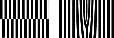
Gratings to produce HG modes (left) or LG modes (right) |
Some other important things that I got out of the talk are that the HG modes and LG modes are both separately complete sets, so either kind of mode can be expressed as linear combinations of the others. It turns out that combinations of orthogonal, &pi/2 out of phase HG modes produces LG modes. This is fairly easy to understand, at least in terms of intensity profiles. Admittedly, my understanding of what an LG mode actually looks like is fairly limited - apparently my notions of polarization and phase were confused. If you slice an LG mode in a given plane, the points all have different phase. Points of the same phase are on different planes, and riding a point of constant phase sends you on a corkscrew. This is distinct from linear or circularly polarized light in which riding a point of constant phase sends you in a straight line. Likewise, you can make the HG modes by adding &pi/2 phase shifted LG modes of opposite topological charge. The radial and azimuthal polarizations that I have been studying come out of this analysis as linear combinations of orthogonal HG modes that are in phase or &pi out of phase. Other phases correspond to so-called 'hybrid' vector beams in which the state of polarization varies (from linear to circular) in a given plane. Dr. Galvez also discussed his current work in trying to entangle laser modes in a similar way to how one might entangle photons.
The second talk was given by Giovanni Milione from City College of New York, a 2nd year phd student who worked in the LTC for some time. Not to repeat the above, he elaborated on the concept of a hybrid vector beam. He showed that you can define a sphere, similar to the Poincaré sphere, for cylindrical vector beams. At the top and bottom of the sphere are the LG modes of +/- 1 topological charge. There are actually two spheres: one in which the (circular) polarization is aligned with the topological charge, and one in which it is anti-aligned. The aligned case leads to the familiar radial and azimuthal - type beams, while the antialigned case leads to the counterrotating beams. Prof. Metcalf noted the fact that the diverging field lines in a radially polarized CVB exhibit some divergence, a fact consistent with what I've read about the theory of CVB's - namely that in making the paraxial approximation for these beams, we start to violate &nabla · E = 0. I'm not sure what the consequences of this fact are, but the fact is that these beams do exist, so the mathematical model must be doing an okay job anyway. It must be that HG and LG modes also violate Gauss' law if these CVB's are just linear combinations of them, though they of course also arise from the paraxial approximation. Giovanni also discussed his work which involved sending light with angular momentum through chiral crystals and observing the differences in optical properties depending on the sense of the rotation (Raman activity).
After these first two talks, all of the high school students gave talks. An interesting aspect of one of the talks was the fact that Giovanni's lab has something called a spatial light modulator, a device that is used to produce an arbitrary diffraction grating using some kind of pixellated LCD matrix. There was also some discussion of a "radial polarizer", an LCD device that seems to operate on the same principles as my space-varying wave plates, except that the birefringent material is liquid crystal, and the birefringence direction is changed with an electric field. A high school student from last year gave an interesting talk on producing a radially polarized beam using a Mach-Zehnder interferometer (essentially by combining modes as above).
My talk went alright, and I was reminded of various things I need to remember when preparing/giving talks. Giovanni raised the question of something called conoscopic interference, an effect produced in uniaxial or biaxial materials when they are hit with light of some divergence, as an explanation of the pattern emerging from the Pringles lid between crossed polarizers. It is an effect I need to learn more about. After the talks, we went to dinner, and we learned a bit more about the visitors.
July 23, 2010
And now for something completely different! I haven't really discussed what I've been doing/learning in Prof. Metcalf's lab since I've been here, and that's largely because I've mostly been learning about the Rydberg atom experiment that's running. Basically the effort is to excite helium atoms to high principle quantum number states because the atoms exhibit interesting properties with electrons in those high energy levels. In particular, the atom size (&prop n2) is very large, leading to a large dipole moment; thus, these atoms have a huge response to applied electric fields, and they are easy to ionize. Because the electrons are far from the nucleus but still bound, it is interesting to see the way in which the orbitals respond to an electric field - in particular, the Schrodinger equation becomes separable in parabolic coordinates (instead of spherical), so there is a mixing of l and m states. It would not be possible to observe this effect if the electrons were tightly confined because the required electric field would be prohibitively high.The experiment takes helium gas and excites it by means of an electric discharge to a metstable (23S1 - long decay time as per selection rules) state He*, which then functions as the ground state. The beam is collimated, and it is then hit by two lasers in rapid succession that propagate perpendicular to the atomic beam. The lasers are red (780-796nm) and blue (389nm). The blue is associated with a transition from the metastable state to a higher energy state, 33P2, and the red is associated with another upward transition to the n = 26 level. The experiment can change the relative position of the beams, which changes the order in which the atoms encounter the laser light. The interesting thing is that the highest efficiency (in terms of population excited to the Rydberg level) is achieved when the red beam precedes the blue beam. This is counterintuitive because we would certainly expect to achieve the highest efficiency by having the blue light first, exciting the atoms from He* to the middle level, and then from the middle level to the Rydberg level. This process is known as stimulated Raman adiabatic passage (STIRAP), and is possible because the red light can establish a coherence between the middle and upper levels even if there is no population in those levels. My understanding of the notion of "coherence" is very limited, but apparently that is the way to think about it.
Obviously there are many, many complexities in actually getting this experiment to work. I've learned a lot about the detection mechanisms for all species involved, and I've attempted to understand the locking systems they use to keep the lasers at the proper frequency. The current mystery is why they are not acheiving 100% efficiency - there is a detector for He*, which shouldn't register at all if all of the metastables are being converted to Rydbergs. I hung around in the lab while they were installing a fiber amplifier, the output of which they now use to push the metastables out of the beam by use of the bichromatic force. The bichromatic force is itself an interesting topic that I now know something about, but suffice it to say that it is a very strong force applied to atoms by laser light of multiple frequencies (hence bi-chromatic).
In an effort to understand why STIRAP happens, I have been studying the optical Bloch equations (OBE's), which is a topic that was briefly touched upon in my intermediate quantum course. This set of differential equations describes the interaction between a two-level atom and a light field, and I see it as a first step towards understanding this more complex (3 level, 2 light frequency) process. Prof. Metcalf explained to me that when we consider the Hamiltonian of the atom + light field, it changes the eigenstates of the system, so that the new eigenstates have parts of the ground and excited states in them. The amounts of each state can be parametrized by a "mixing angle", a function of the rabi frequency and detuning. This notion generalizes to the 3-level system in which 2 mixing angles are involved. While I'm not sure if I'll be able to completely understand the analytical picture, I certainly can write code to solve differential equations! I've written down the OBE's as a function of the ground and excited state populations, and the real and imaginary parts of the coherence. In reality, the system only has 2 variables (constraint on populations, constraint on coherence because it's a pure state), but I chose 4 because they were easy to write down and make checking the code easier. The Rabi frequency can be chosen to be real because we can choose an overall phase for the wavefunction to make this so (the overall phase has no physical meaning). The differential equations reduce to:
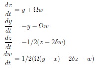
In the above, x is the ground state population, y is the excited state population, z is the real part of the coherence, and w is the imaginary part of the coherence. Frequency is normalized to &gamma, so time is normalized to &gamma -1. I used a 4th order Runge-Kutta scheme to solve the differential equations with a step size of 0.0005. Using this code, I have reproduced a figure I found in Metcalf's book for &delta = -1.0 and &Omega = 1.0; I have also observed Rabi oscillations for large &Omega - their amplitude decreases and frequency increases as detuning is increased, as expected. Both &Omega and &delta can be functions of time, and 4th order accuracy is preserved.
|
|
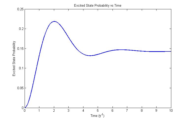
In the first plot above, &Omega = 1.0, &delta = -1.0. This plot is identical to one of the first few figures in Prof. Metcalf's laser cooling book. In the second, &Omega = 1.0, and the detuning is varied: &delta = 0.0 (blue), -1.0 (green), -10.0 (red). We note that as the detuning is increased, the effective Rabi frequency increases, and the amplitude of oscillation decreases. All curves converge to the steady state value for the excited population which is lower for large detuning.
July 22, 2010
We put an order in at the machine shop to fabricate the assembly that will hold the plexiglass window and apply stress to it.
|
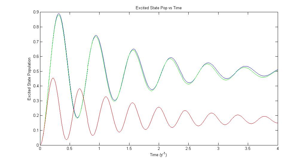
In the above, one square is 1/8 in. by 1/8 in. A 1/2 in. diameter polished plexiglass disk is at the center of the assembly. The plexiglass disk is slip-fit into a 1/2 in. diamter, 1/8 in. thick copper ring. The purpose of the ring is to distribute the stress more uniformly across the circumference of the plexiglass and to prevent the screws from boring into the plexiglass. The part of the assembly that will ultimately apply the stress consists of a 1 in. inner diameter, 2 in. outer diameter section of aluminum tubing. The aluminum ring has 3 threaded holes for 1/4-20 screws (quarter inch diameter, 20 turns/in., the same screws as the optical tables) spaced 120o from each other. It is the screws in these holes that will ultimately apply the stress to the sample. A fourth 1/4-20 bore will be threaded on the flattened bottom of the assembly, which will allow me to mount the optic on a Thor Labs stand. The longitudinal width of the plexiglass disk and copper ring are matched at 3/8 in., while the aluminum ring has a width of 5/8 in. in order to accomodate the screw bores.
While the Spilman and Brown paper does not specify the dimensions of the outer ring with the screws that applies the stress, I imagine that the precise dimensions of that part of the assembly are not critical. The amount of stress (400psi) is apparently not very large, so the above assembly should be able to produce the desired amount of stress in the sample. Concerned about ease (cost) of fabrication, we asked the machine shop to find a piece of copper tubing that most closely matched the 1/2 inch diameter, 1/8 inch thick parameters above, and then cut the plexiglass to that diameter. The diameter of the disk shouldn't have a dramatic effect on the birefringence because those kinds of effects should depend only on the optical path length through the disk. Based on my visit to the machine shop yesterday, they did seem to have plexiglass of various thicknesses, from which they should be able to produce the desired (3/8 in.) thickness. I noted that the thickness of the disk is quite large compared to its diameter, and I imagine that the reason for this is because a thin disk may deform in unpredictable ways under stress. The 1/4-20 screws should be able to apply fairly uniform stress over the longitudinal extent of the disk because their diameter is comparable to the thickness of the disk.
In the meantime, I have been reading about the theory and various uses of unconventionally polarized beams. The azimuthally polarized beam can be understood as the mode to which the TE01 mode in an optical fiber couples in free sapce, and this comes out in solving the vector Helmholtz equation in the paraxial approximation. Radially polarized beams can likewise be thought of as the free space analog of the TM01 mode in an optical fiber. The theory of these cylindrical vector beams has been quite thoroughly worked out. One paper claims that the ordinary linearly polarized Gaussian beams (including HG and LG beams) can be constructed from this basis set, though I don't understand how you could add up beams with 0 amplitude on the axis to make a beam with finite amplitude on the axis. Also, solutions to the vector paraxial Helmholtz equation do not satisfy Gauss' law, but their divergence can be minimized by choosing certain parameters properly. Presumably it is beams with these properly chosen parameters that are closer to actually existing in free space.
In terms of usefulness, the notable feature of radially polarized beams in particular is their behavior under focusing: radially polarized beams can focus their longitudinal component far better than LP or CP beams. I'm not precisely sure why this is, but it's clear from symmetry concerns that focusing a radially symmetric polarization structure down to a point is more likely to produce constructive interference than is linearly polarized light. This strong longitudinal component can be use for lithography or high precision imaging. An interesting application is focusing a radially polarized beam to normal incidence on a metal. The high intensity longitudinal field can induce second harmonic generation in gold on silicon or other substrates. I imagine that the polarization singularity itself must have some interesting topological properties (apparently it is a vortex of topological charge 1). It seems like we should be able to associate some angular momentum with an azimuthally polarized beam, which makes me wonder whether a focused, azimuthally polarized beam could be used to apply torque to samples being optically tweezed. Because these interesting polarizations do have distinct uses, finding a way to produce them cheaply and easily seems like a valid direction of inquiry.
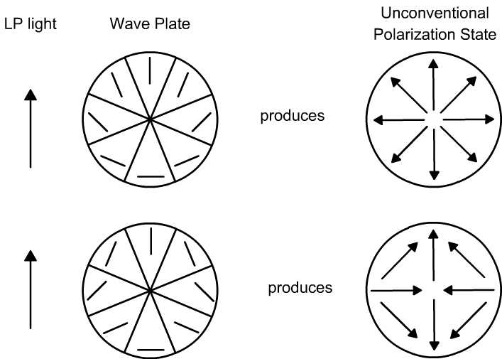
...The optic is here! Its mechanical function is exactly I describe above, though the dimensions are a bit different (photos will follow). I used the screws to apply some stress and observed a stress pattern similar to the results from Spilman and Brown. Using LP laser illumination, I placed the optic in front of a rotating analyzer. The resulting image exhibited a central small dark bar/lobes that rotated in the opposite sense to the rotation of the polarizer. This behavior matches the description of the discrete, counterrotating wave plate discussed below, so it is reasonable to argue that the near-axis portion of the beam exhibits the polarization resulting from that pattern (the second picture under 'unconventional polarization state' below).
July 20, 2010
Dr. Noe pointed me to a paper by Alexis K. Spilman and Thomas G. Brown in which stress birefringence is used to make a spatially varying wave plate that can be used to produce radially or azimuthally polarized light. The basic notion is fairly easy to understand - if the orientation of the fast axis of a half wave plate varies across the perpendicular surface of the plate, any polarized light normally incident on the plate will exhibit a spatially varying polarization when it emerges from the plate. The paper discusses discrete wave plates that can be made very cheaply (they used Staples brand tape as the birefringent material) that can generate discretized versions of radially polarized beams or beams with counterrotating polarization (counterrotating compared to the azimuthal angle).
|
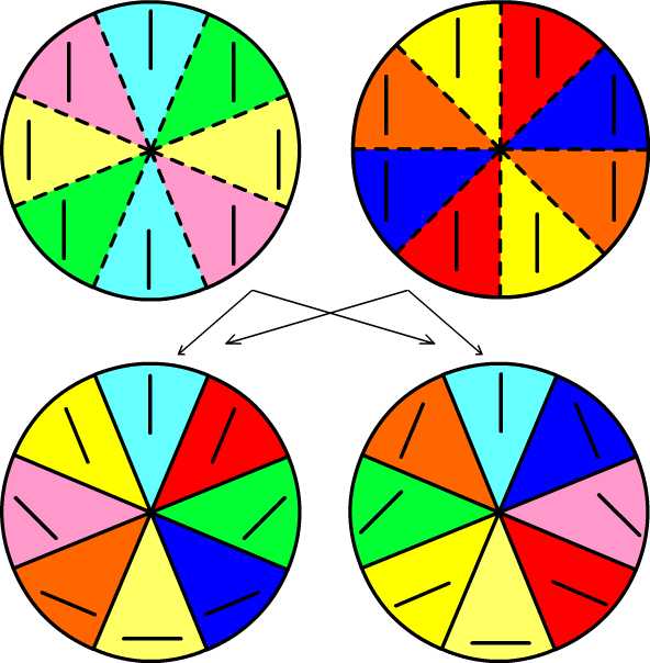
In the above graphic, the lines on the wave plates represent the fast axis orientation. I have made an effort to duplicate the optic they describe using a polymer laminate pressed between two glass windows. Due to some interesting symmetries, I was able to make both plates using only two circle-cut pieces of laminate.
|
Note in the above how each plate has wedges whose origin alternates between the left and right initial circles. In principle, we could make an arbitrary number of cuts (perhaps 2n if we wanted the symmetry to only need 2 initial circles?) to get a smoothly varying fast axis orientation, which would produce a truly radially polarized or counterrotating beam.
Having made both of these wave plates, I first tested them by putting them between two crossed linear polarizers. The first polarizer was my laptop screen: the LCD display produces polarized light, and the RGB pixels can produce fairly monochromatic light. Rotating the second polarizer, the dark bands in the wave plate rotated in the same sense for the radially polarizing plate, and in the opposite sense for the counterrotating plate. These observations are consistent with the notion that the light emerging from the wave plates has the desired polarization.
I mean to replicate the next few results of the paper, which involves acheiving a continuous spatial variation in a wave plate by means of stress birefringence. Spilman and Brown applied m = 3 (triangular) symmetric compressive stress to an optical quality BK7 glass window with two methods: screws located every 2&pi/3 around the circumference, and using the differential thermal expansion of BK7 and copper. Because BK7 is fairly expensive, and the machining required seems complex, I will try to demonstrate the same principles with some kind of polymer. According to the Plastics Technology Handbook by Chanda and Roy, most plastics have stress-optical coefficients that are many times higher than those of glass, so the stress required to produce birefringence is much less than for glass. They define the stress-optical coefficient as the amount of stress a 1 inch thick piece of material has to be under in order for it to exhibit a dark circular ring between crossed polarizers (indicating half-wave retardance). They claim that for most plastics, the figure is ~6.9 MPa/in. Thus, for a 1-cm thick window made of plexiglass, which is likely more readily attainable, the stress required would be around 2.7 MPa (400psi) compared to the 52 MPa calculated in the paper. This is about 20 times less stress, and seems like a more easily realized laboratory setup.
In the meantime, I have been examining the numerous very thin (mm) transparent plastic surfaces that I encounter throughout the day for their stress birefringence properties. While many of these materials do exhibit both intrinsic and stress birefringence, the fact that they are so thin makes controlled deformation very difficult - the bending needed to achieve the kinds of required stresses produces undesirable deformation. An interesting and well-understood property that I have observed is that stress birefringence can be produced when hot plastic is pressed in a die or mold, and then frozen in when the plastic cools. This represents another possible method by which spatially-varying wave plates could be produced. In this case a thin, hot plastic sheet could be pressed into some shape such that the stress distribution in the plastic produces the desired spatial distribution of fast axes, and then the plastic would be allowed to cool, freezing in the desired distribution. Obviously a die or mold applies a transverse compressive stress as opposed to radial, so this method does not appeal to the theoretical analysis in the Spilman and Brown paper. Nevertheless, due to the large number of circular plastic items produced by pressing that I encounter ever day, I imagine it might be worthwhile to see if one with the desired stress distribution already exists.
Katya gave me the lid of a Pringles can which exhibits some interesting birefringence properties. It appears to have been molded, and the punching out of the cylindrical part of the sides certainly applied some radial stress, as is evidence by a noticeable bulging out of the central disk. Between crossed polarizers it exhibits both concentric rings of light and dark, in addition to a pair of orthogonal dark bands that rotate at half the rate of the analyzing polarizer. It may be that this pattern is consistent with an m = 4 symmetric stress pattern, though I need to make sure I understand what m = 4 should look like (square?). In any case, it seems that there are some interesting polarization effects going on, which I plan on looking into further.
July 15, 2010
The data from yesterday is fairly difficult to interpret. Based on the theoretical calculation and the geometry of the setup/properties of the fiber, there should be a retardance of -230o per turn. I rotated P2 and took transmission measurements, then fit sin(x+&phi) curves to it in order to determine &phi, the direction of polarization. From the -230o from the calculation, we would expect that undoing one turn would cause a relative retardation of +230o. This would transform LP light into light of some elliptical polariation. 230>180, so the major axis of the polarization ellipse would be aligned with a direction orthogonal to the initial linear polarization. 230 - 180 = 50 ~ 45, so we might imagine that the ellipticity (here defined as minor axis / major axis where 0 corresponds to LP light) would be around &radic(2) = 1.414. Furthermore, undoing two turns would cause a retardance of 460o, and 460 mod 360 = 100 ~ 90, so undoing 2 loops should function as a quarter wave plate. The data doesn't really support either of these predictions, and I believe that it is because the rubbery outer sheath of the fiber contributed to the amount of bend/twist in the fiber in an unpredictable way.The problem of the fiber sheath could be overcome by using fiber with less sheath material, and the problem of mode sweeping in the HeNe could be overcome by using a different laser. Presumably if these improvements were made, the experiment would be able to verify the theoretical result calculated below.
July 14, 2010
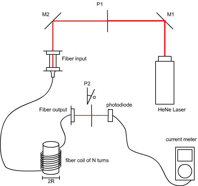
I've put together an experiment that I hope will be able to demonstrate the equation for the retardance of a bent fiber:
|
In the above, M1, M2 are mirrors, and P1, P2 are polarizers (P2 can rotate). Assuming that a constant intensity beam of polarization defined by P1 passes into the fiber, we would imagine that any change in the polarization that we observe at the output end is due to stress-induced birefringence in the fiber. By measuring the change in polarization vs the number of turns or total distance wrapped, we should be able to extract the retardance/length for a given value of r and compare it with the equation calculated below. Next, by varying R, it should be possible to verify the 1/R^2 dependence of the retardance.
Mode sweeping in the HeNe laser is a big problem, and the laser typically takes 2+ hrs to warm up. Adjacent modes in a HeNe laser are orthogonally polarized, so as the modes drift around, the light transmitted through P1 varies considerably. P1 is oriented 45 degrees to the natural axis of the laser to minimize the effects of mode sweeping, though this instability causes some uncertainty (~15%) in polarization measurements.
July 7, 2010
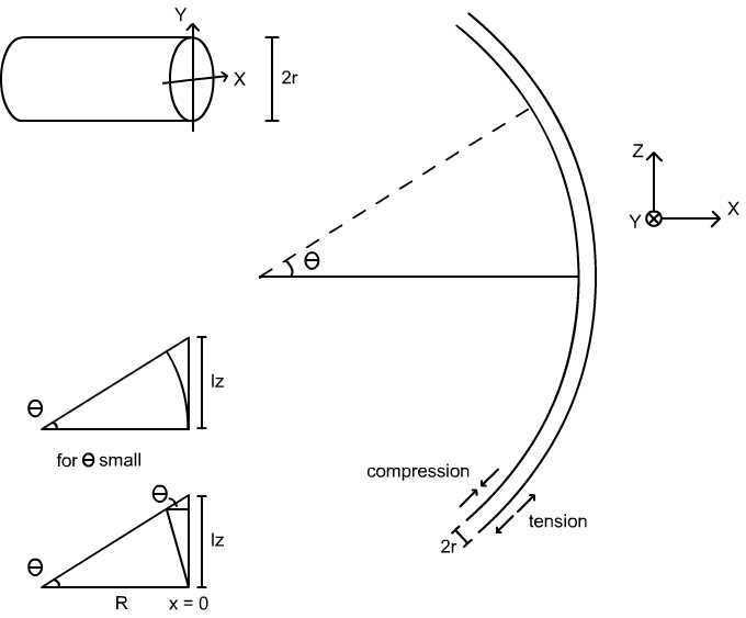
I am definitely intrigued by the stress-induced birefringence concept. I found a few of the papers referenced by the thesis that had mentioned the fiber polarization controller, and one of them (by Ulrich et al) has a good explanation of birefringence from bending and how it can be used to rotate polarization.
|
It's fairly clear that &Delta lz/lz = &epsilonz = x/R (based on similar triangles in the lowermost part of the figure), so the stress in the z direction, &sigmaz, is &sigmaz = x/R * E where E is Young's modulus. The next part of the derivation is not so clear because it involves finding the &sigmax to the presence of &sigmaz. Finding &sigmax is important because it is in introducing an asymmetry in stress in the x and y directions that we can get birefringence and a rotation of polarization. The papers simply state the result:
They claim that this result comes from "elementary mechanics", but I've talked to multiple mechanical engineers, and they are not sure where the formula comes from. It makes some intuitive sense - &sigmaz is compressive on the inner part of the loop and tensile on the outer part, so we might imagine that the inner part is squished outward while the outer part is drawn inward, so there could be some stress due to the different amounts of deformation. My first thought was that it was due to Poisson's ratio - the notion that a stress in the z will cause deformation in the x, which we could associate with a stress in the x direction, but Poisson's ratio does not appear in the result above. This leads me to believe that it is a purely geometric effect (in that it doesn't involve material properties).
The rest of the derivation is fairly clear - we integrate over the width of the fiber to find:
In the above, &kappa = 1/R is the radius of curvature, and we note that &sigmax(+/- r) = 0 because those are free surfaces. Next, we introduce the elasto-optic coefficients pij, which basically represent the tensor relationship between the speed of light in a material and the strain that the material is under. Assuming small changes in index due to bending, we find:
From basic notions of stress and strain and the definition of Poisson's ratio mentioned above, we find that:
Combining the last 3 results, we can calculate the change in index in the x and y directions and take their difference to find the birefringence &beta :
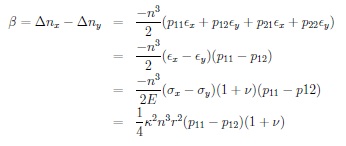
In the above, n is the index of the material with no bending, pij are the elasto-optic coefficients, &sigmai and &epsiloni are the stress and strain in the ith direction, and &nu is Poisson's ratio for the material. From the first line to the second, we recognize that p11 = p22 and p12 = p21 because the material is isotropic and homogeneous in the sense of its elasto-optic characteristics (it may have some intrinsic birefringence).Thus, we can calculate the birefringence due to bending solely from material properties. For silica, we find that:
This effect turns out to be large compared to other sources of birefringence (i.e. twisting, intrinsic birefringence), so it can be used to rotate polarization in a predictable way. This is how the fiber polarization controller is able to rotate polarization by bending the fiber around circular arcs. Based on the fiber diameter, one can calculate the number of turns required to produce an arbitrary phase shift in the two orthogonal polarizations of light in single mode fiber. Thus, we can construct wave plates by changing the phase by specific amounts (&pi / 2 for quarter wave, &pi for half wave, etc).
Fine adjustment of the fiber polarization controller is accomplished by an angular offset of the loops relative to each other, introducing controlled twist into the fiber. It is not immediately clear that such a deformation should cause birefringence - twisting the fiber around its axis produces symmetric stress in x and y, so the index change should be the same. In a different paper, Ulrich et al find that this birefringence is a result of coupling between the two orthogonal modes in the fiber. Though the analysis is very complex, I understand that for weak twist, the polarization simply rotates with the twist of the fiber. For stronger twist, the full mechanics of EM perturbation theory must be employed, which is something that I don't yet understand.
July 1, 2010
Katya gave her talk this morning on geometrical optics. One
interesting question that was raised was how to actually prove the
focusing properties of various mirrors. We started with a spherical
mirror and showed, using the small-angle approximation, that the focal
length of the mirror is R/2 where R is the radius of curvature.
It got me wondering what would happen if you didn't use the small
angle approximation. I knew that the problem could be solved because
I was very interested in this sort of thing in high school, and I remember
finding some expression that reduced to R/2 if you assumed small angles. I
fumbled around for a while, then Vince pointed out that a certain pair of
angles were the same, which led to a solution by the law of cosines.
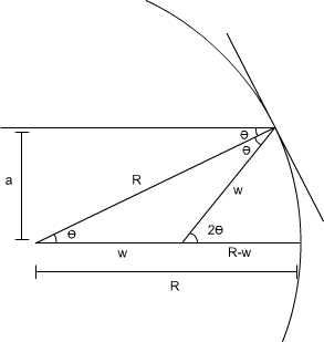
|
We can tell that the place where incident horizontal lines intersect with the axis of the lens depends on the angle theta, or the perpendicular distance from the axis a. It's also clear that for a << R, as for small theta, all incident horizontal lines are focused to a point at R/2. We note that the focal length in the optical sense would be (R-w), but the expression for w is cleaner. The fact that all lines do not converge to a point results in spherical aberration - presumably this proof would not work for a parabola (because it is known that parabolas focus to a point), though I'm not totally sure what would be different. Later on we showed an equivalence between the definition of a parabola in terms of a focus and directrix and a definition in terms of focusing with Fermat's priciple where all paths of horizontal incoming rays reflecting through the focus should have the same length.
June 30, 2010
Spent most of the day in the conference room. First was Vince's talk on the wave nature
of light, then later on was the weekly group meeting. Everyone discussed what they were
interested in, and I talked about what I had learned about the fiber polarization controller.
The idea is that single-mode optical fiber by itself is very weakly birefringent, and non
PM (polarization-maintaining) fiber will tend to rotate the polarization of the input light in
an unpredictable way. It is desirable to be able to rotate the polarization of linearly polarized
light in fiber in order to correct for the above effect. Wave plates can be used to rotate the
polarization of light, but their usefulness depends on wavelength, and they tend to be very expensive.
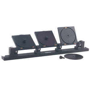
There is a device called a fiber polarization controller that is used to rotate the polarization of
light in fiber. It consists of a series of paddles in which the fiber is wound around a circular trough. The
stress due to the winding of the fiber causes birefringence in the fiber, which rotates the polarization of
the light traveling through the fiber.
|