Calibrating an Optical Tweezers
Imaging System Using Diffraction
Faye-Marie Vassel and John Noé
Stony Brook Laser Teaching Center
Introduction
My motivation for this project stems from my interest in biophysics. Biophysics is a multidisciplinary field that applies the principles of chemistry and physics to understand how biological systems function. After expressing this interest to Dr. Noe, he informed me that one of his students, Hamsa Sridhar, was currently working in the lab on optical tweezers and that I should look into tweezers. That conversation prompted me to research optical tweezers. Aftering reading several articles on tweezers and their uses I was definitely able to see their relation to biophysics.
Essentially,optical tweezers are a laser based technique that utilizes minute forces, usually in the piconewton range, to measure and manipulate biomolecules. Optical tweezers have been used to trap viruses, bacteria, small strands of DNA and a host of other molecules.
While I did not successfully tweeze any molecules, I was able to see yeast cells being tweezed, which was pretty awesome.The focus of this project was the calibration of the optical tweezers imaging system. Specifically, we used diffraction to calibrate the imaging system. Ultimately, we were able to use diffraction to determine the magnifications of the microscope's objective lenses and compare our values to those obtained previously in Dr. Noe's lab.
Optical Tweezers Setup
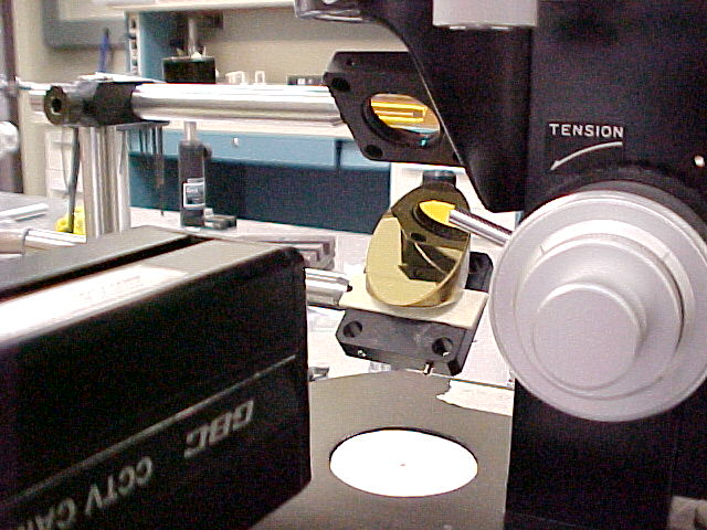
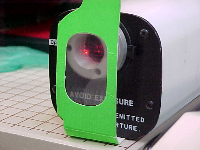
An important part of the tweezers setup is the imaging system. The imaging system is comprised of several components. The primary components of the imaging system are: the CCD camera, the screen, a gold mirror positioned at 45 degrees, and the microscope's imaging system (i.e. illumination; objectives lenses).
The inverted tweezer system I used in the LTC was setup by Hamsa Sridhar, I was actually able to watch her use the setup to tweeze yeast cells which was very helpful in my overall understanding of tweezing.
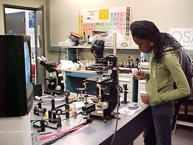
This shows me with Hamsa's inverted tweezers setup.
Calibrating the Rainbow Glasses by Diffraction
One of the first things we did was use the rainbow glasses as a diffraction grating. We used Young's double slit experiment equation, d=(m* lambda)/(sin[theta]), to determine the distance "d", which essentially is the object spacing. We used a red laser of wavelength 633nm and shone it through the rainbow glasses towards a whiteboard. This effect produced a diffracting pattern on the board and from this pattern we measured the distances between the m= 0 order and m= -1 and 1 orders. We calculated the distances between these orders and obtained an average value of 27.72 cm. We also measured the distance from the laser to the board, distance "L", to be approximately 212 cm. We used the average distance between the orders, "y", and the distance "L" to detemine the angle formed by using the equation arc tan (y/L) = theta. Having obtained these values we were able to calculate the angle, subsequently, we used this angle to determine sin(theta) which was about 0.13.
Having obtained these values we were then able to determine the distance "d", which we calculated to be 4.88 microns. This is quite interesting because one of Dr. Noe's students, Hamsa, calculated a value of 4.87 microns, which highlights a level of consistency between our respective values.
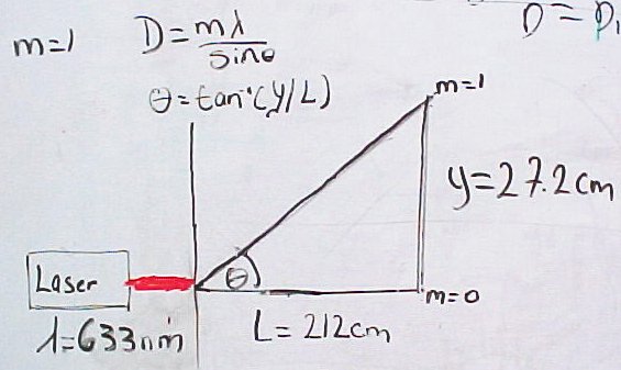
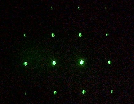
These are pictures from the rainbow glasses calibration: "Young's Slit Diagram"; Laser and Rainbow Glasses ; Diffraction Pattern w/ green laser.
Imaging the Rainbow Glasses
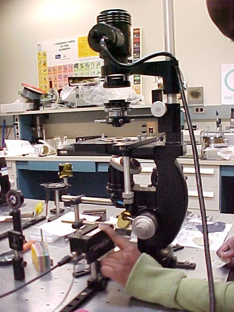
For this portion of my project we imaged the rainbow glasses under both the low power and high power objective. We did the latter to find a way to determine the magnification of each lens. We first imaged the glasses under the lower power objective( 20x). Following this I used a plastic sheet to mark the position of the dots produced. I did this for 11 dots and a total of 5 times. Following this I measured the distance between the first and last dot. After measuring this distance I divided this value by ten. We followed the same procedure for the remaining trials and obtained an average value of 7.69mm.
We followed the same procedures for the high power objective( 50x). By doing the latter we obtained an average value of approximately 20mm. Having obtained the the image distances for both objectives we subsequently were able to calculate the magnification for both lenses.
Using the equation for magnification, M=d*/d, we were able to determine the magnifications for both objective lenses with d= 4.87mm and " d*" differing for both lenses. For the 20x objective we obtained a "d*" of 7.69mm and by plugging this into the magnification equation we obtained a magnification of 1600.
For the 50x objective lens we obtained a "d*" of approximately 20mm and using this value we obtained a magnification of 4010. Taking the ratio of these two values yields a proportion of 5/2. This value is consistent with the magnification of a 50x objective in comparison to a 20x objective lens.
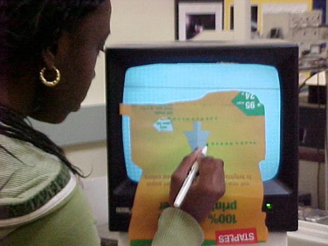
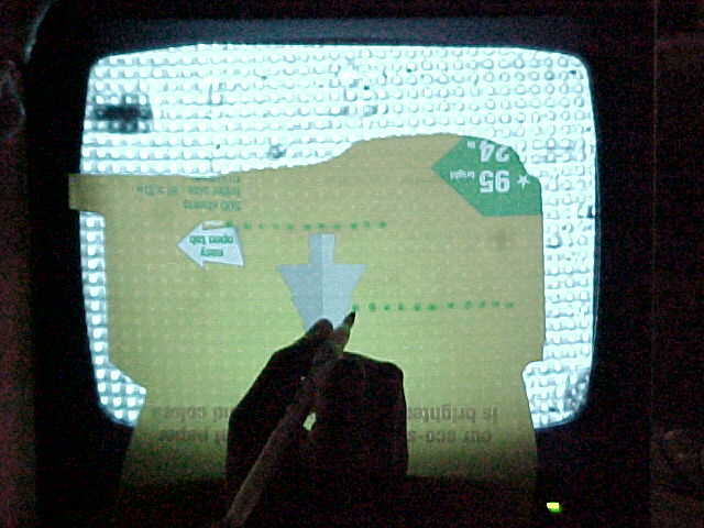
This shows me marking the spacings of the image produced on the screen under the 20x objective.
Measuring Yeast Cell Diameters
Having obtained the maginifications for the 20x and 50x lenses and having them in the right proportion enables us to apply this information to other areas. An example of how we can utilize this information is in determining the actual diameters of imaged yeast cells. This being the case we imaged yeast cells ,under the 50x objective, and measured their diameters on the screen. The diameters we measured averaged about 2cm. By knowing this distance we were then able to determine an approximate object diameter. We did the latter by using the the magnification of the 50x objective and employing the equation for magnification to determine the yeast cell's actual diameter.The value we obtained was approximately 5 microns.
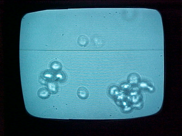
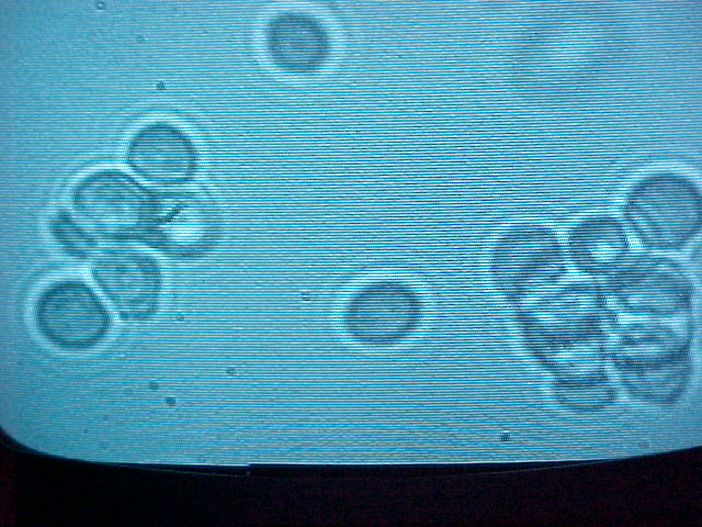
These are pictures of the yeast cells we imaged under the 50x objective.
Conclusion
While determining the actual diameter of yeast cells we arrived at a road block. Previously, a couple of Dr. Noe's students calculated the actual diameter of yeast cells and they obtained a value of about 10 microns consistently. However, this differs greatly with the value, 5 microns, that I obtained during my project.
While doing outside research on yeast cells I came across information that discussed the variablity of yeast cell diameters. From the information I came across I gathered that the Common Baker's yeast cells ,most likely that used in the lab, have a diameters ranging from 5-10 microns. Interestingly, this information is consistent with the value I obtained and the value obtained previously in the lab.
| Faye-Marie Vassel February 2008 |
Home Laser Teaching Center |