Report - Frustrated Total Internal Reflection and the Evanescent Wave
An Introduction to Evanescent Waves and Frustrated Total Internal Reflection:
It is often believed that no light is transmitted during total internal reflection. However, due to Maxwell's equations, we know that an electromagnetic field cannot end suddenly at an interface. Instead, a standing wave known as the evanescent wave is formed. The evanescent standing wave decays exponentially and does not propagate; therefore, it can be referred to as an evanescent field.
An interesting phenomenon associated with the evanescent field is the frustration of total internal reflection. If we shine a laser through a prism so that the light hits the glass-air interface at an angle beyond the critical angle, we will be able to observe total internal reflection and an evanescent field is formed. If however, a second prism is placed within a few wavelengths of the first prism, the evanescent field can be coupled and the laser light is transmitted through the second prism. This is frustrated total internal reflection.
Setup:
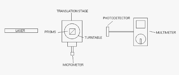
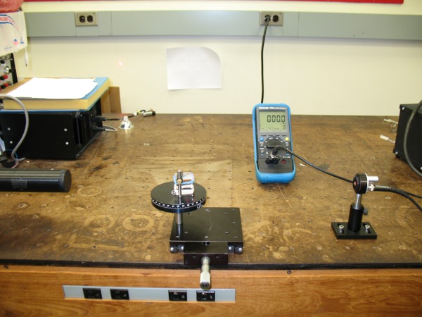
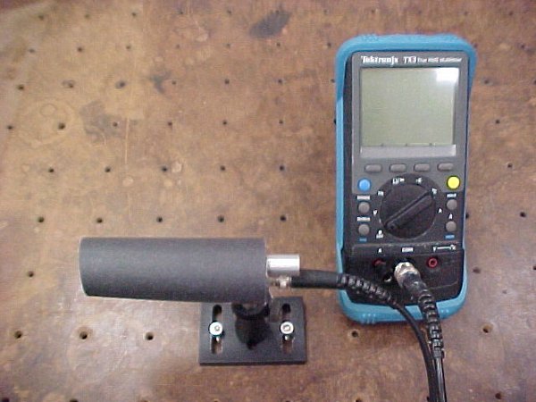
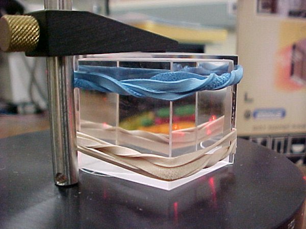
This is a drawing of my setup. The laser is a polarized Melles Griot that is 62 cm long. The prisms are arranged as shown in the drawing held together by two rubber bands. A piece of nickel foil (approximately 12μm thick) is placed between the two prisms at one end, creating a triangular air gap. The prisms are mounted on a vernier turntable (see pictures below) that can measure angles to within five minutes of a degree. The turntable is screwed on to a translation stage that is equipped with a micrometer screw. The prism array can therefore be rotated and translated. A photodetector is connected to a multimeter to measure the intensity of the transmitted light.
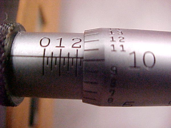

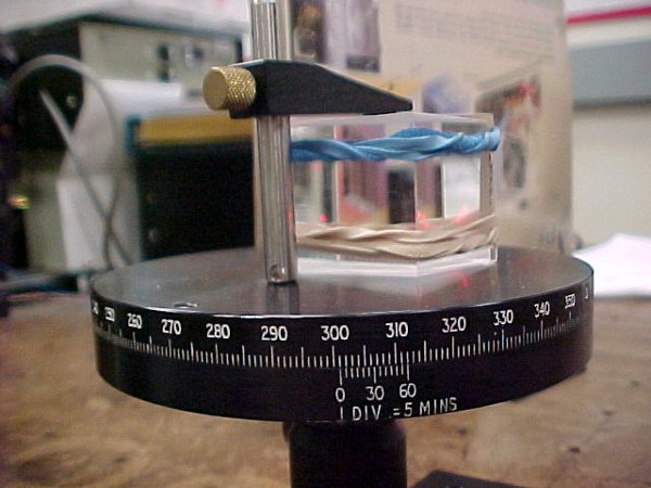
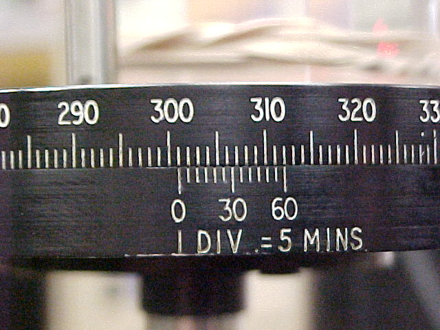
The turntable is equipped with a vernier. To read the angle, look where the bottom "0" line is in relation to the upper scale. Then, find where a tick on the bottom lines up with a tick on the top, that is the minutes measurement of the degree. For example, in the above picture, the angle is 301° and 30 minutes, or 301.5° .
Data Analysis:
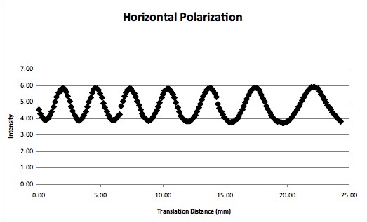
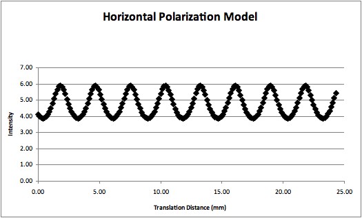
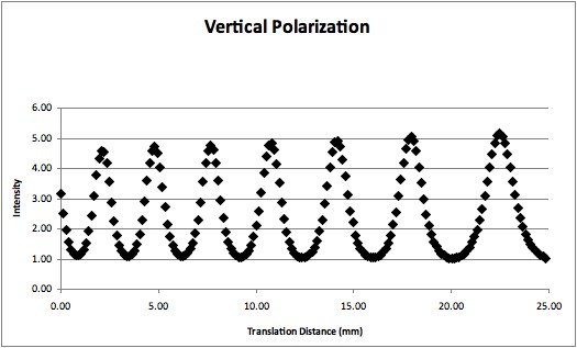
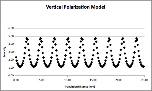
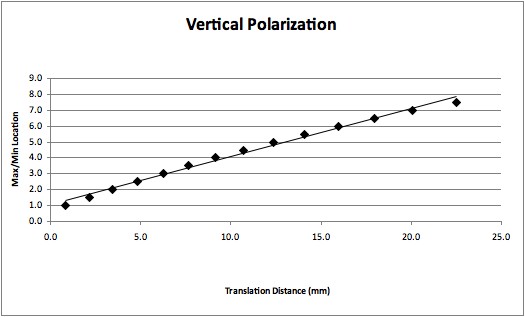
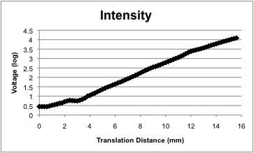
First the setup was rotated at an angle before the critical angle so that FTIR was not achieved. The setup now acts as a Fabry-Perot etalon and multiple reflections are observed. Data was taken on the intensity of the transmitted light as a function of the translated distance of the setup. As the air gap widens, we see that the transmitted intensity follows a pattern. Compared to the model, we see that the actual data shows a fanning as the critical points become progressively farther from each other. This is likely due to fact that the prisms are not perfectly flat. This data was taken with the laser horizontally polarized and vertically polarized.
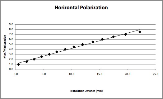
These graphs demonstrate the fanning of the data. The location of the critical points was graphed against the translated distance. If the distance between the critical points was constant, then the plotted points would fall on a straight line instead of on a curve.
Next, the setup was turned so that FTIR was observed. Data was taken on the intensity of the evanescent wave as a function of gap width and translated distance.
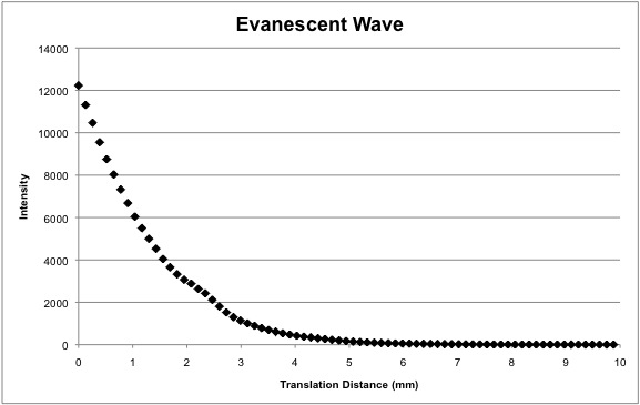
As the air gap increases in size, we see that the evanescent wave decays exponentially.
Dennis Chen |