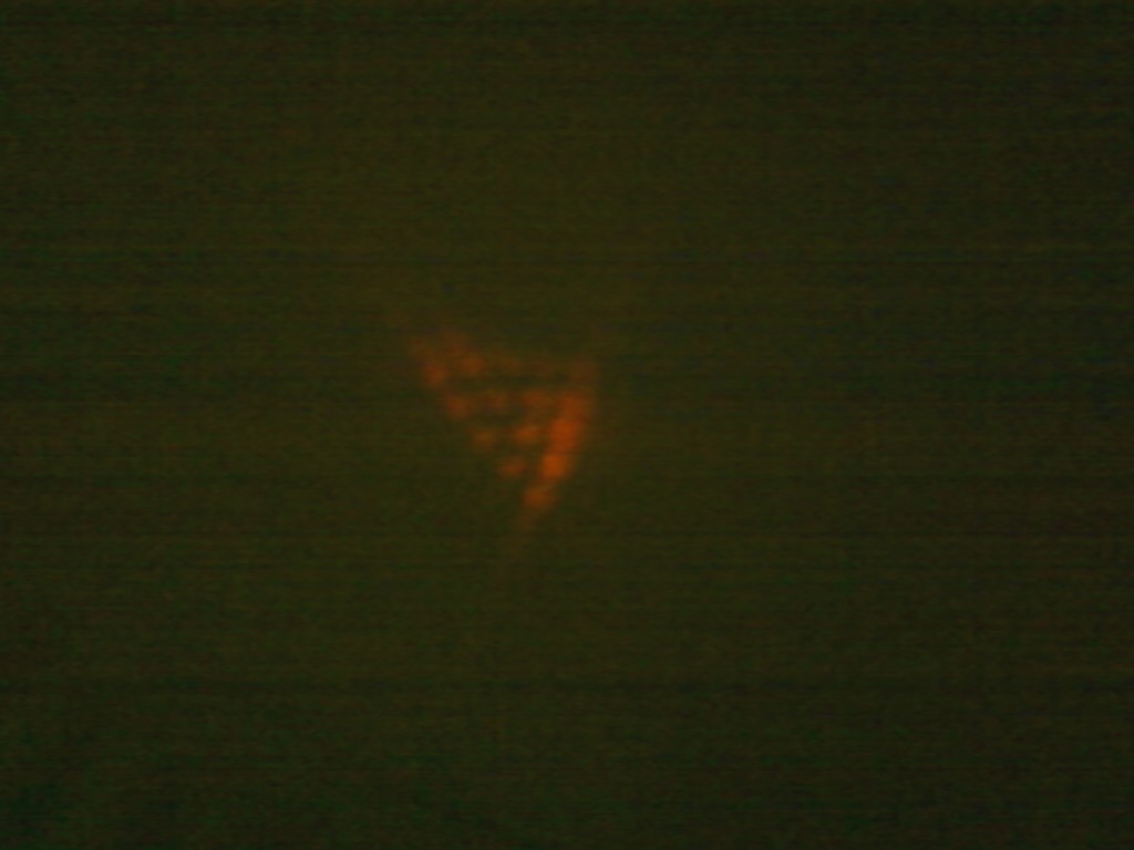
Triangular Aperture
This is an interesting pattern I observed when I used a LG beam of higher radial index with my triangular aperture. It was an LG 21 beam (the input beam was an HG 12) and it appears to be more of a hexagonal pattern as opposed to a triangular pattern. I'm interesting in exploring the relationship between the diffraction pattern and the radial index more thoroughly. One problem may be where to put the aperture for a LG beam multiple concentric circle since there are now multiple dark rings instead of one dark core.
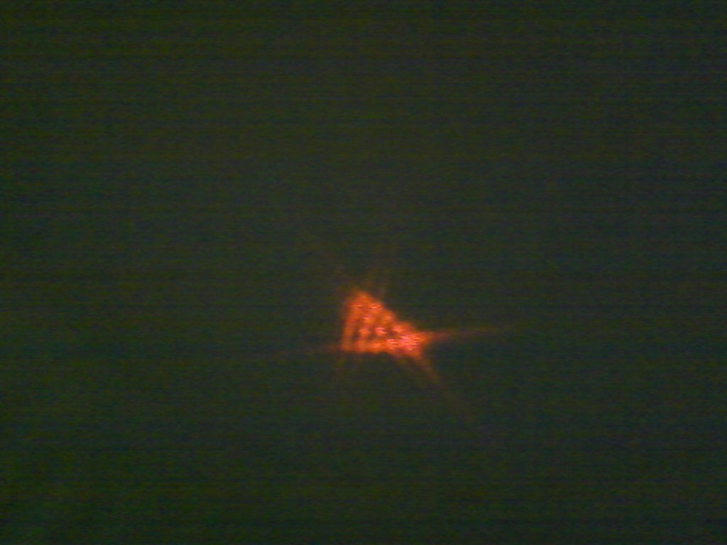
This is the pattern I observed for an LG 40 beam, ie a beam with topological charge 4. The pattern is as expected, a triangular lattice with 5 points on each side.
This is the pattern for an LG 40 beam, but with the topological charge reversed. I was able to reverse the charge by rotating the cylindrical lens by 45 degrees. Its 30 degree rotation with respect to the aperture is opposite that of the previous beam as expected.

Here the input beam had a topological charge of 2 and the diffraction pattern observed matches previous experiments.
Single Slit
This is the diffraction pattern for an LG beam passing through a single slit. It's similar to that of a regular laser, but with a dark band in the center. It's interesting to note that for a double slit pattern with an LG beam the helical phase differences affects each band of the diffraction pattern and alternated, but for the single slit it just creates a single dark band.
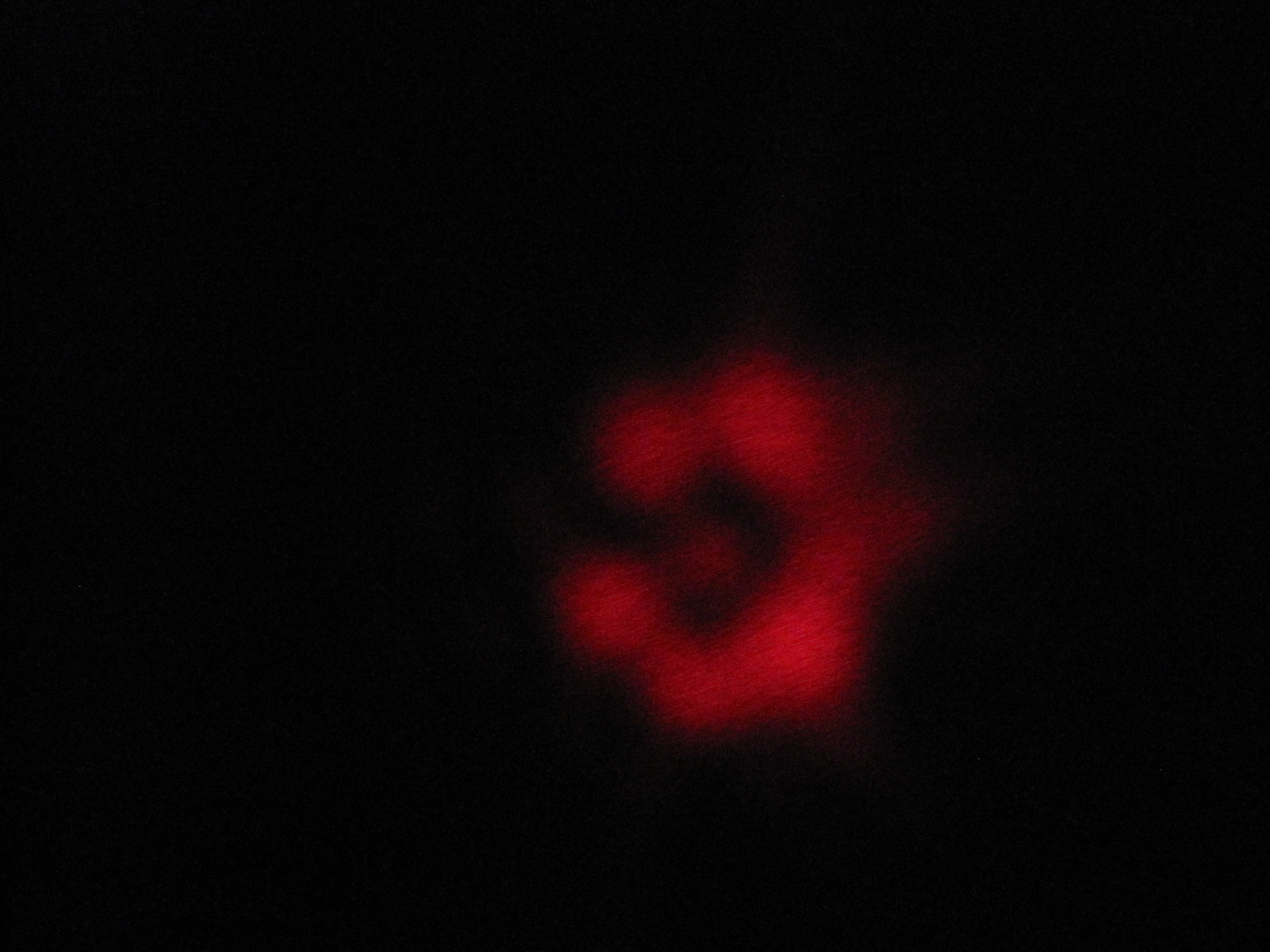
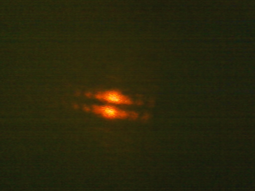
Circular Aperture
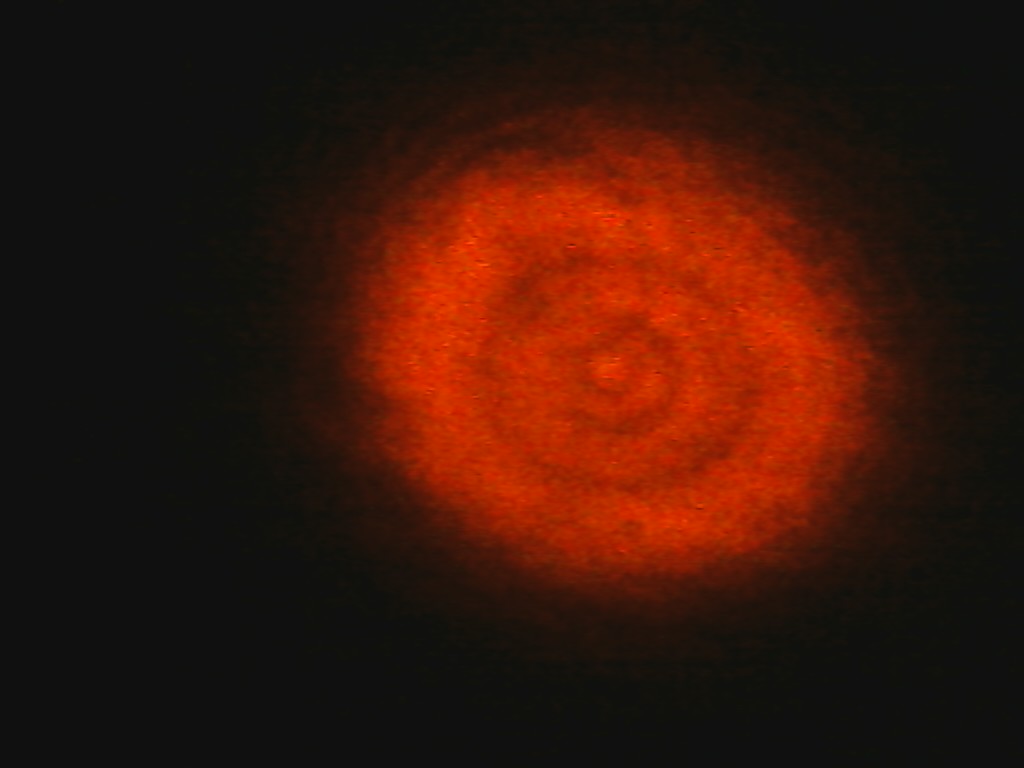
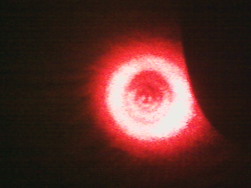
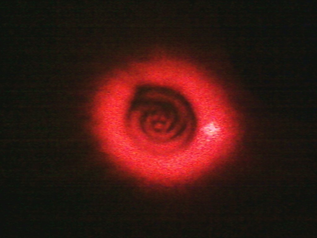
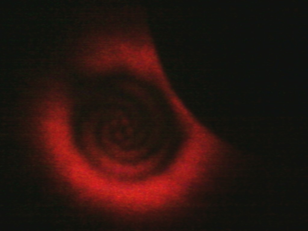
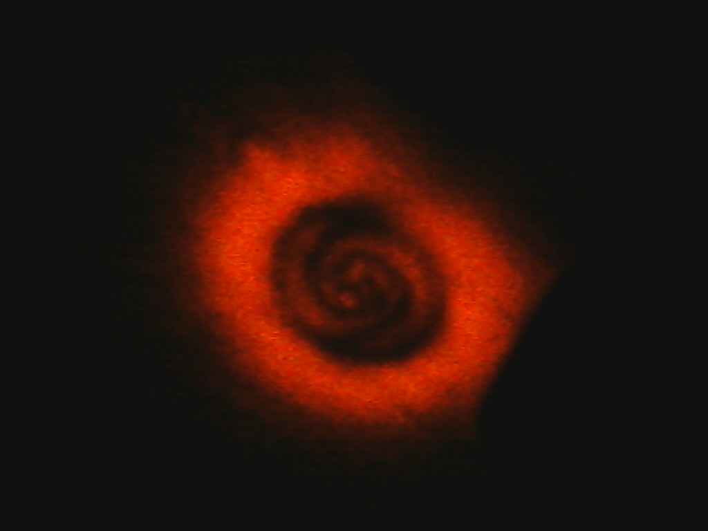
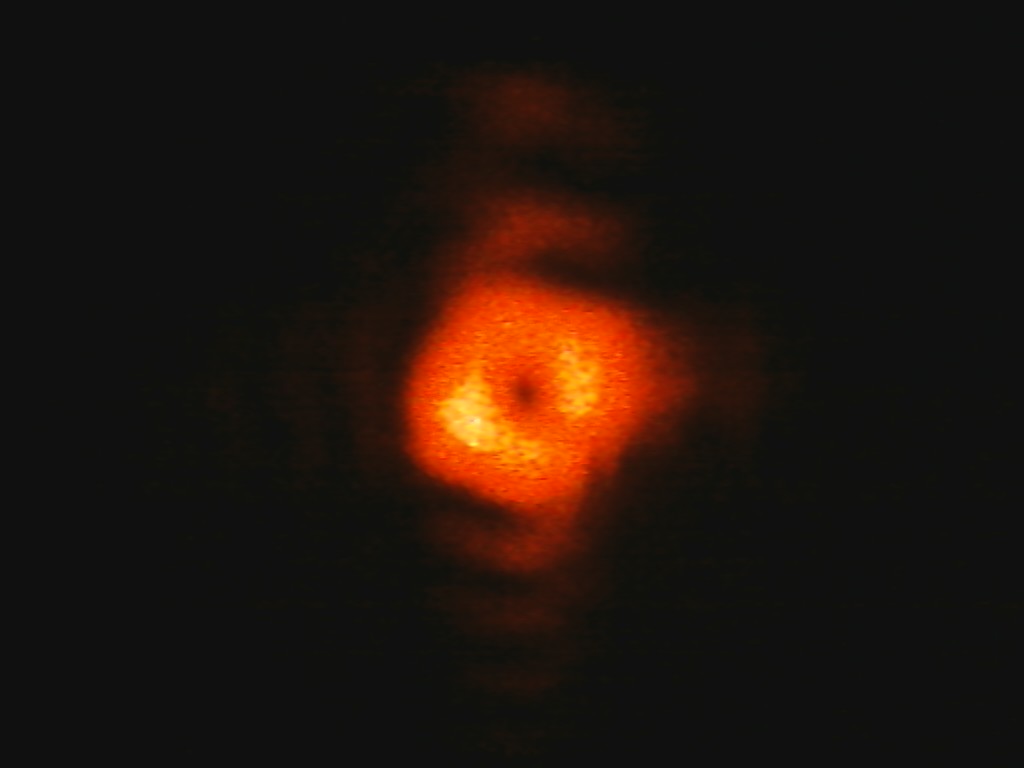
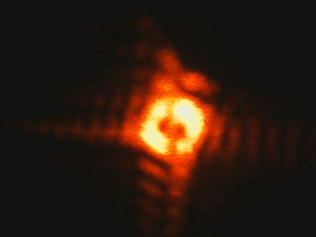
In this experiment I used a 1mm diameter circular aperture to diffract the LG beams of varying azimuthal index. Two lenses were used to focus the image until the patterns seen below came on the screen. The interesting thing is what happened after the pattern first appeared and the second lens was translated forward. The pattern at the center of the beam would rotate as it would rotate more spirals would form around it. This can be seen very clearly in the case where the charge is 3 and 4 in the pictures below. When the charge is 1 obviously the pattern can't rotate as it's only a point, but more rings were formed around it as the lens was moved and it would oscillate between being a dark and bright spot.
One interesting observation concerned how fast the center pattern would rotate versus the charge. I tested this using the 1mm circular aperture and I moved the second focusing lens one inch. For the charge 1 beam I saw the center spot go from bright to dark to bright again, corresponding to a 2*Pi phase shift. For the charge 2 beam the pattern rotated 180 degrees (phase shift of Pi). For the charge 3 beam it rotated by 60 degrees (2Pi/3) and for the charge 4 beam it rotated by 90 degrees (Pi/2). This is an interesting pattern and it would be useful to test this with different sized aperture.
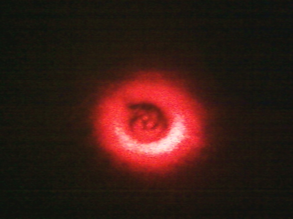
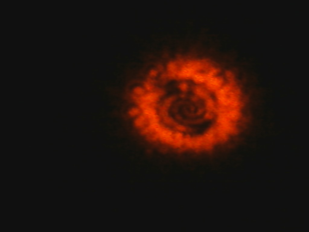
I also tested how the rotation of the pattern depended on the sign of the charge. I know from previously that rotating the mode converter by 45 degrees will result in the sign of the charge being reversed. After I reversed the charge I noticed that the rotation was also reversed ie moving the second lens toward the screen would result in clockwise instead of counterclockwise rotation. Finally, with the charge 3 beam there is a noticeable spiral around the central three points so I tested how that pattern depends on the sign of the charge. Sure enough, after reversing the sign the pattern reversed and that can be seen in the pictures below.
In terms of the size of the aperture, using a smaller one (.5mm circular aperture) I saw a similar pattern but when the second lens was moved, the pattern would rotate slower.
Charge=2:
Charge=3:
Charge=4:

Reversing sign of LG30 beam:
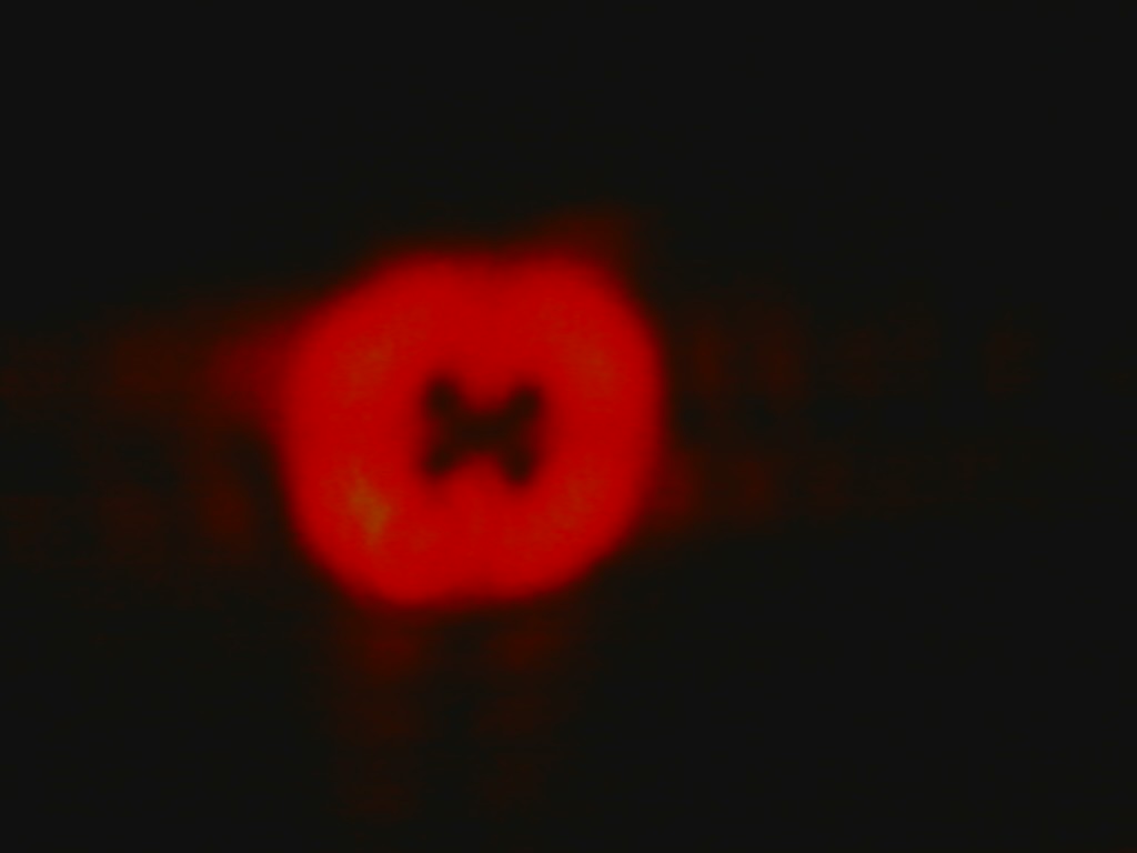
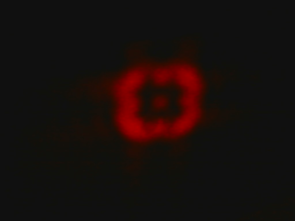
Rectangular Aperture
Disclaimer: The rectangular aperture I used was homemade, ie I cut out a rectangular hole in a sheet of brass using an exacto knife. I will be replacing these pictures with better ones once I have a more accurate aperture.
Charge=1:
Charge=2:
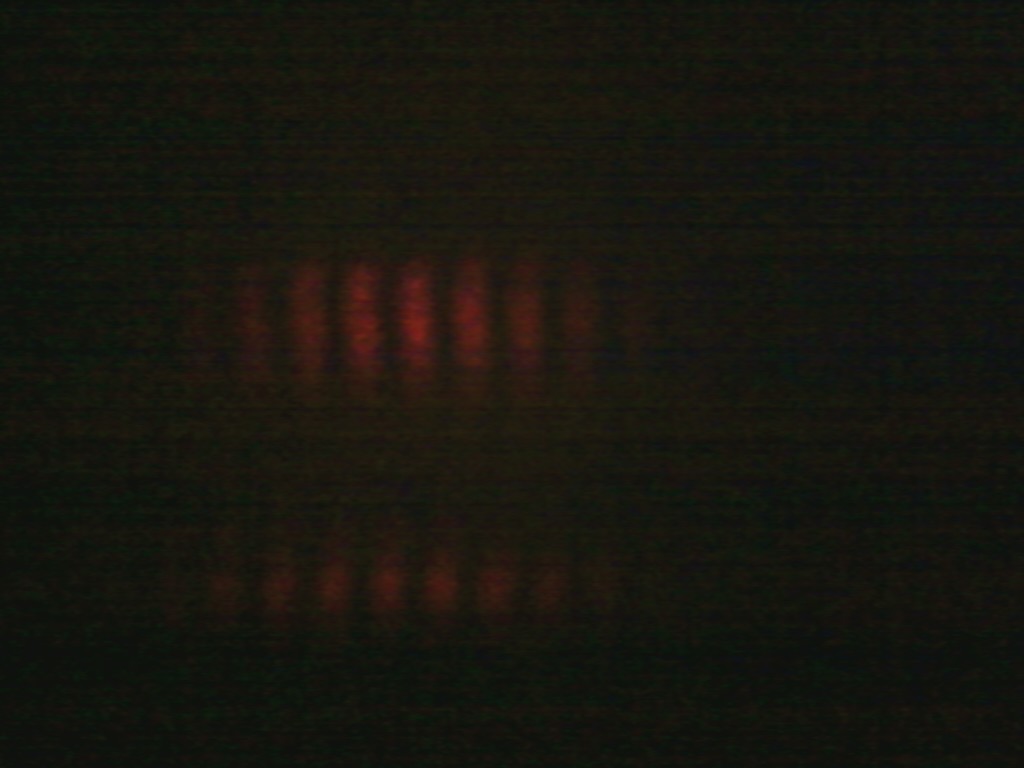
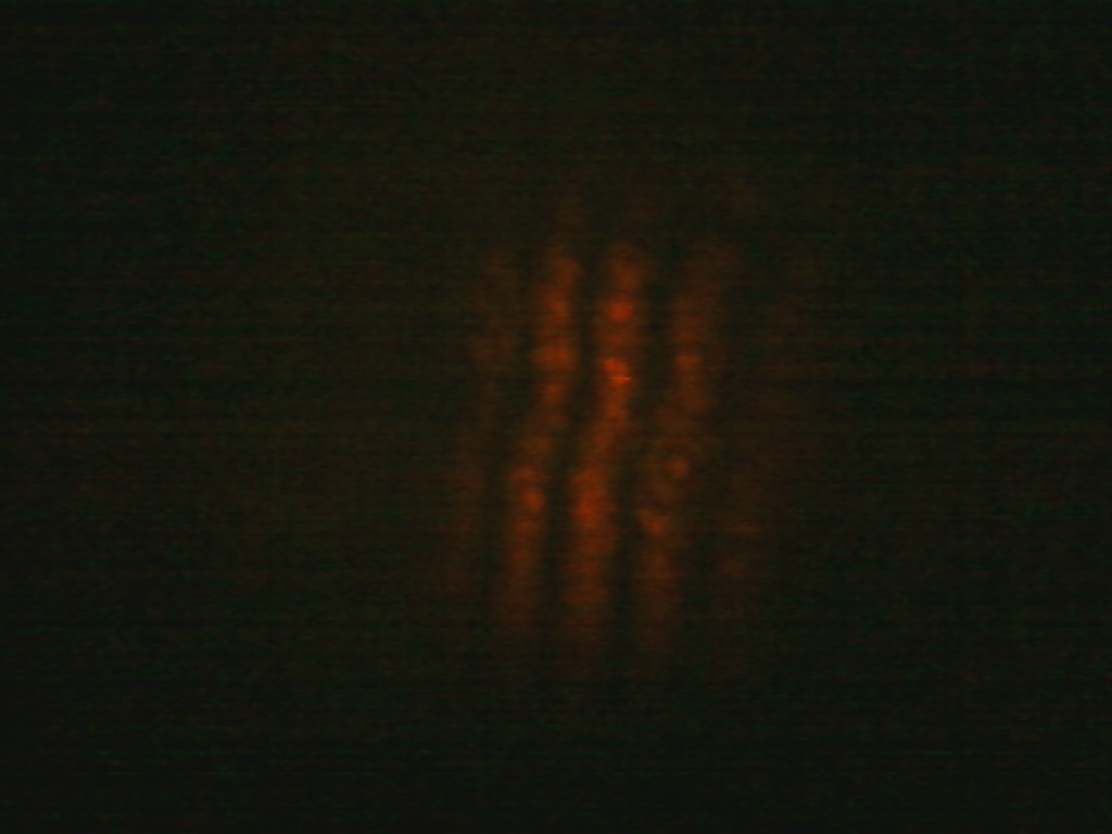
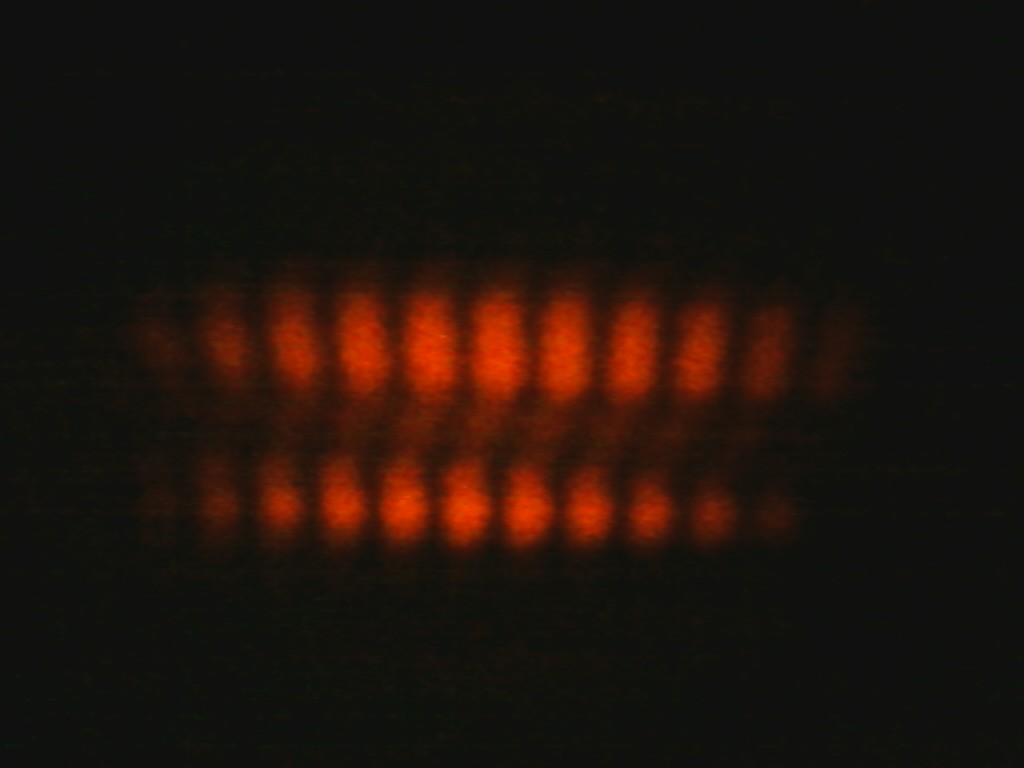
Double Slit
Below are pictures taken after a LG beam has been diffracted using a double slit set up. It can be seen that compared to a regular light beam in this set up, the LG beams have a slanted pattern due to their azimuthal phase dependence. There is a difference in pi between the bottom and top part of the band, meaning that when one constructively intereferes the other will constructively interfere. This explains why directly above one dark spot is a bright spot and vice versa.
It can also be seen that the pattern depends on the topological charge of the beam. As the charge increases the middle part of the pattern becomes lighter and lighter and it becomes easier to distinguish each band of light.
Charge=1:
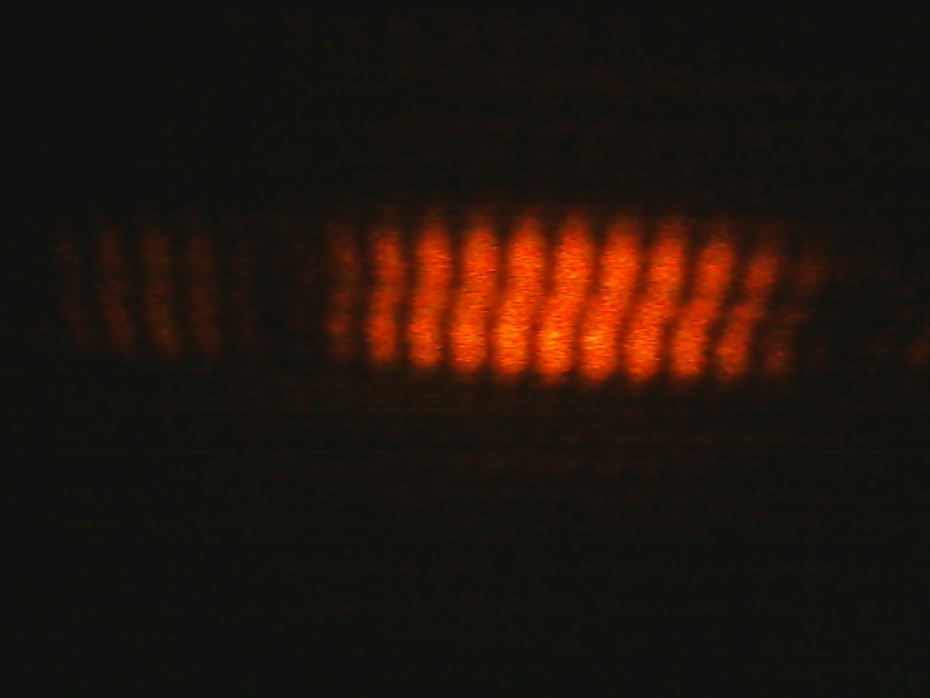
Charge=2:

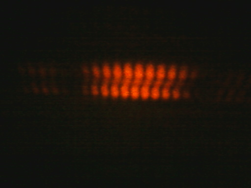
Charge=3:
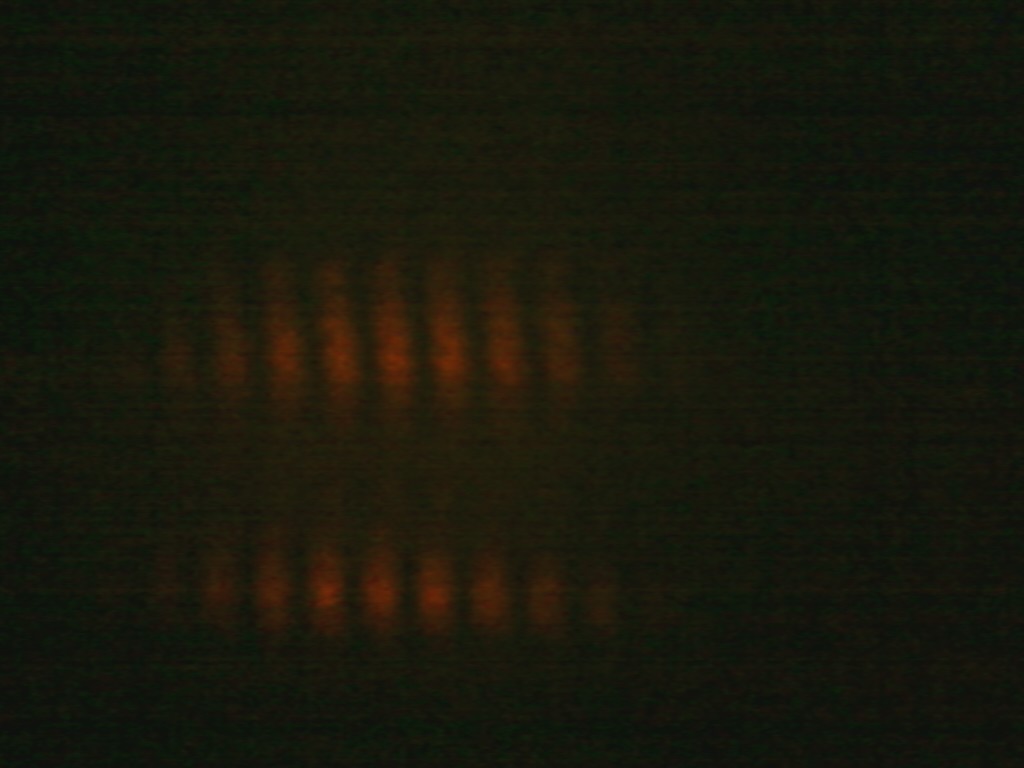
Charge=4: