Research Journal
Monday, September 9th, 2013
The ΔE energy difference I calculated previously for the Zeeman splitting resulting from this magnet corresponds to the frequency difference between one of these curves, m = ± 1 and the frequency for which m = 0 . The curve corresponding to the transition from one m=0 energy level to the other will not appear due to the geometry of the setup (Dr. Metcalf explained why this is true but I'm still confused by it). The left and right circularly polarized modes lie in the left and right lasing curves respectively. The right circularly polarized modes correspond to transitions in which the magnetic quantum number increases by one, and the left circularly polarized mode correspond to a decrease of one. During such a transition the orbital momentum quantum number l changes, which in turn changes the angular momentum L. This change in angular momentum is conserved in the circular polarization of the emitted light.
As the laser warms up the modes sweep across the lasing curve. When the mode is amplified in the overlap region it is split apart by mode pulling. This is a phenomena that occurs in all kinds of oscillators, not just lasers. The modes are pulled away from their position calculated from Δf = c/2L toward the center of the gain curve. Lasing lines are pulled in the direction where the gain is greater.
Wednesday, July 17th, 2013
The Herbach and Rademan laser is finally in the Magnet Assembly that Sam sent me! It's not the exact same laser as before, but it's the same model. However, this one has a heater wrapped around it, so I can speed up the mode sweeping. I used half and quarter waveplates to convert the left and right circularly polarized moeds to linearly polarization, so they can be sent to different photocells by a polarizing beam splitter. The non-polarizing beam splitter I used sends a portion of both polarizations to the first photocell. They are sent through a 45 degree linear polarizer so that their polarizations are the same(along the same plane) so that they can interfere with one another. The polarizing beam splitter, as I said before, sends the oppositely polarized modes(there should be about two at any given time in such a short laser) to two different photocells so they can appear on two different channels on the oscilloscope.
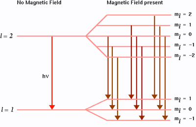
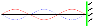
According to Sam, my previous thoughts on the Zeeman
splitting were somewhat incorrect. The magnetic field does not directly
split the lasing lines themeselves, it splits the lasing(gain) curves:
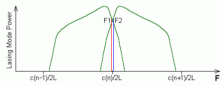
Image taken from Sam's Laser FAQ
Monday, July 15th, 2013
The six inch Herbach and Rademan laser is finally up and running, thanks
to Sam! Interestingly, although not suprisingly, it was originally part of
a bar-code scanner(probably an old one at that). I managed to mode match
it into Metcalf's SFPI, whoe piezzo is driven by the Spectra-Physics
Driver we
have in the LTC (the same one I used last week, I just forgot to mention
it). I got a pretty nice spectrum--the FSR is easy to make out, which is
about 1.6 GHz:
c/4L = 3×10⁸m/s / 4(0.50m) = 1.6GHz
In this case, the FSR is c/4L and not c/2L because, in the case of a spherical mirror SFPI such as the one I am using, any light ray goes back and forth four times before escaping the cavity. The setup of my SFPI's cavity is confocal, in which the identical spherical mirrors are separated by a distance equal to their radii of curvature so that their foci meet at the center of the cavity. In this way, higher-order spatial modes that normally arise and crowd up the oscilloscope screen in a spherical-mirror FP overlap on another, for a clean picture of the FSR.
Friday, July 12th, 2013
I finally succeeded in mode matching into Metcalf's SFPI! I didn't stop at just one laser though--after Laser Sam fixed up the thermally stabilized HeNe, I replaced one of the mirrors in my setup with a non-polarizing beam splitter and matched that laser into the Fabry-Perot as well. I was able to fine tune the FP tilt in order to get a clear picture of the Free Spectral Range of both lasers on the oscilloscope. I used irises to manually control which lasers I wanted to study at any given moment. I used a polarizer to block out some of the light coming out of the second laser, because there was too much to easily read the data on the oscilloscope.
Monday, July 1st, 2013
My idea for this "Zeeman Laser" experiment has intrigued my fellow students and advisors, but before I can take any action I must make sure that the project is feasible and design a stable set-up.
The main goal of the project will be to observe the effect of Zeeman Splitting in a HeNe laser using a Scanning Fabry-Perot Interferometer (SFPI). The "scanning" part comes from the fact that the length of the cavity oscillates, changing the frequencies that are successfully transmitted; this results in a scan that usually occurs over at least a few multiples of the FSR. This is made possible by attaching a piezoelectric material to one end of the cavity. This is an interesting material that expands when a voltage is applied to it. By applying an oscillating voltage from a function generator or driver, one can make the piezoelectric expand and contract periodically, causing the cavity length to oscillate at a desired frequency.
In order to actually observe the split spectral lines caused by the Zeeman effect I will need to use an SFPI with a high enough resolution. Unfortunately, the SFPIs that we currently have in the LTC do not have a high enough resolution. Dr. Noe and Sam Goldwasser claim that if I use those SFPI I will not be able to separate the closely spaced Zeeman lines. The peak widths would be too large in comparision with the spacing between the peaks. This peak width is determined by the reflectivity of the mirrors; the higher the reflectance coefficient, the more narrow the peak widths will be, resulting in a higher resolution. I'm not sure how to get around this; we may have to order new mirrors from THORLABS, but even them I'm not sure if it would be a good idea to replace the mirrors on some of the SFPI we currently have.
Despite that minor setback, I do have an idea for producing my magnetic
field, that I can't believe I didn't think of before. It would be annoying
to hold magnets around the laser, especially if I had to construct mounts
for them. I would have to go through the trouble of making sure that the
magnetic field was approximately the same coming from all directions and I
would have to figure out how to get powerful magnets in the first place!
So, instead of using a magnet to generate a magnetic field, I could do it
the old fashion way with a current though a wire. A coiled loop of
wire--a solenoid-- would be perfect for this situation, I think,
because of the ease of setup. Yes, I would have to supply a power source,
which I would not have to do in the case of using magnets, but no or extra
THORLABS parts will be needed, because all I need to do is wrap the
solenoid around the laser. I might want to use some clamps or tape to keep
it in place, but other than that it should be fairly simple. I'm sure I
can find suitable wire and a power source, the only question is if I would
be able to create a magnetic field strong enough to create significant
Zeeman splitting. Now I currently don't know the resolution of the SFPI
that I will be using-- or if I will have one at all--but it can't hurt to
make some estimates. The strength of a magentic field produced by a
solenoid is given by:
B = μ0 n I
where μ0 is the permeability of free space, which is
equal to 4π × 10-7 V·s/(A·m),
n is the turns per unit length of the solenoid,
and I is the current through the wire. A typical solenoid is represented
in the diagram below:

Above image taken from Hyperphysics
A current that I might be able to expect to generate from a power source
would be about 5 A. If I can wind the solenoid say, 600 times along the
length of say, one third of a meter, then the magnetic field produced is
only about 100 Gauss, or .01 Tesla. Pluggin this value into the Zeeman
Splitting equation to deteremine the energy of the new states, we get a
value of about 9 × 10-26 joules, or about 6
× 10 -7 eV. I will be able to resolve these lines if
this energy difference is greater than twice the Full-Width at
Half-Maximum (FWHM) of a peak from this SFPI. According to G. Hernandez,
this width can be calculated as follows:
FWHM = 4 sin-1 [ ( 1 - R ) ( 2 R1/2 )-1 ]
Where R is the reflectance coefficient of the mirros of the SFPI,
squared. It must be noted that this is given in Radians (it is
dimensionless). It can be converted to energy or frequency units if one
knows the free spectral range (FSR) of the SFPI, which marks the
repitition of spectral peaks every π radians in the interference
pattern. The FSR is given by:
Δσ = (2d)-1
where d is the length of the SFPI cavity. It must be noted that this is
given in wavenumber, or inverse wavelenght. If a 2 inch cavity
is used, like the ones we have in the LTC, then the free spectral range in
joules is approximately 6.5 × 10⁻²⁵ joules. Now, the following condition must be
satisfied:
ΔE > FWHM × FSR / π
Plugging in the desired forumula and conditions into the equation above,
we find that the minimum required refletivity is about 96%. That is
certainly doable, but that is a fairly high coefficient for such low
standards. The Finesse of the cavity, the ratio of the FWHM to the FSR,
for such a setup will only be about 21. An SFPI with high finesse will
have sharper transmission peaks and lower minima. In order to get the
best data possible, one would ideally like a finesse of several hundred or
even a few thousand if possible. Even by making some overestimates, these
numbers just aren't up to par.
I will have to find another magnetic field source. Sam Goldwasser has suggested using actual magnets to generate it, in fact he has offered to send a laser magnet assembly designed specifically for the kind of experiment I'm trying to do. He claims that it can produce fields in the range of 250-350 Gauss, which is much better than the solenoid. With that kind of field the Zeeman splitting would be up to about 3 × 10-25 Joules or about 2 × 10⁻⁶ eV. With such a magnetic field mirrors of only 87 % reflectiviy are required, but of course we will aim for 99 % for the best resolution and finesse possible.
Wednesday, June 26th, 2013
I'm currently interested in using a Fabry-Perot interferometer to investigate the Zeeman effect. This effect is the splitting of atomic energy levels in the prescence of a magnetic field. My idea is to use a Fabry-Perot interferometer to separate the closely spaced energy levels in order to observe this Zeeman splitting.
The electron is a charged body that orbits the atomic nucleus with a magnetic moment μ that is dependent on its orbital angular momentum L

Above image taken from jick.net
μ = -e L / 2 me
where e is the elementary charge and me is the electron mass. If the atom is in the prescence of a magnetic field which is not aligned with the electron's magnetic moment, it will exert a
torque on it, causing it to precess at a frequency that is proportional to the strength of the magnetic field.
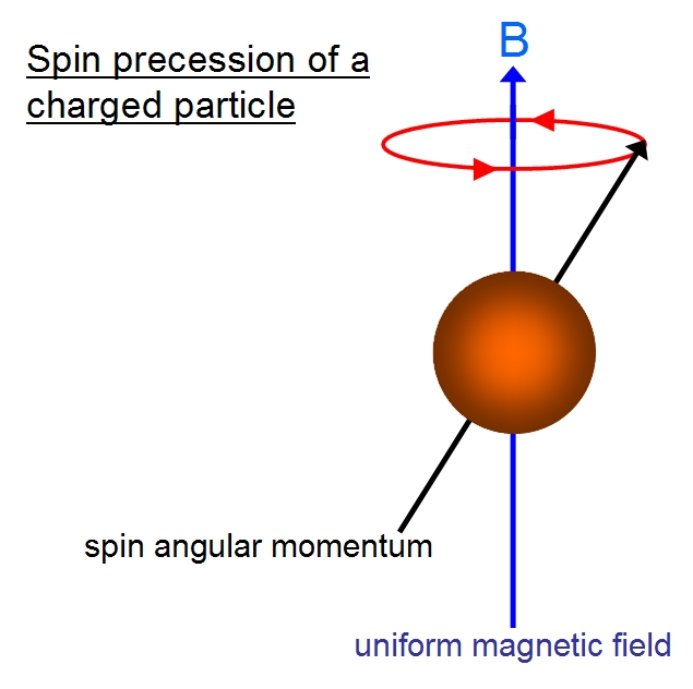
Above images taken from cronodon.com and hyperphysics.phy-astr.gsu.edu
The magnetic potential energy associated with this interaction can be calculated as follows:
VM = -μ · B
= e/2m Lz B = ml eℏ/2m B
This means that there are more possible energy levels that the electron can exist in within a particular subshell (s, p, d, f etc) depending on the orbital angular momentum. For a particular subshell with an azimuthal
quantum number ℓ, "there are 2 ℓ + ℓ integral magnetic quantum
numbers m
ranging from -ℓ to ℓ, which restrict the fraction of the total
angular
momentum along the quantization axis [parallel to the magnetic field] so
that they are limited to the values m"(Wikipedia, Magnetic Quantum Number). The relationship between the quantum numbers is demonstrated in the table below:
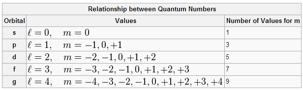
Above Image taken from Wikipedia
The additional available states in the subshells result in the Zeeman
splitting of the atomic energy levels. The new possible states will be
equally spaced and displaced from the zero field (the state within that
subshell for which m = 0) by
ΔE = mℓ eℏ/2me B = mℓ
μB B
where μB is the Bohr magneton, the magnitude of magnetic
dipole moment of an orbiting electron with an orbital angular momentum of
one ℏ, which Niels Bohr called the ground state.
Above image taken from ucdavis.edu
The image above shows the Zeeman effect on atomic energy levels. It can be seen that there are not only more possible energy states for the electron, but more possible energy transitions as well. It is evident that this process obeys the selection rules, that the magnetic quantum number cannot change by more than one unit in any single energy transition.
When Pieter Zeeman discovered the effect bearing his name the electron
spin had not yet been discovered. It is now known that the spin of an
orbiting electron will affect its total angular momentum and thus its
magnetic moment. If the magnetic moment is affected, based on the
equations above, the energy difference of the Zeeman splitting will be
affected as well. The Anomalous Zeeman effect takes this into account.

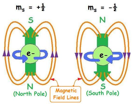
Above images taken from nitt.edu and chemwiki.ucdavis.edu
The images above demonstrates the angular momentum contribution from the spin of the electron. A rotating charged body, like an electron, will create a magnetic dipole moment with a north and south end. A magnetic field will exert a torque on this magnetic moment just as it did with the dipole created by the orbital angular momentum of the electron, which will contribute to the energy of the Zeeman splitting.
When accounting for the spin angular momentum of the electron, the magnetic dipole moment is calculated as follows:
μ = -μB g J/ℏ
= -μB ( gℓ L + gs S )/ℏ
J is the total angular momentum of the electron, while L and S are the orbital and spin components. The g-factor is related to the gyromagnetic ratio between the magnetic dipole moment and the angular momentum of the electron. The two factors, gℓ and gs have been measured experimentally to be 1 and approximately 2.00231... respectively, the latter being one of the most accuratelly measured constants in physics to about twelve decimal places.
As stated before, due to the torque that the magnetic field exerts on the
magnetic dipole moment, the rotational axis of the electron will precess.
In the case of a weak magnetic field, the orbital angular momentum and
spin angular momentum are no conserved separately, but the total angular
momentum is conserved. The angular and spin momentum vectors precess about
the constant the total angular momentum vector. The average of these
vectors over the time domain are simply the projections of those vectors
onto the total angular momentum vector:
Substituting these average values into the equation for the magnetic
moment of the electron, then plugging that into the equation for the
magnetic potential energy, we obtain:
The term mj is the z component of the total angular momentum,
and gj is the Lande g-factor:
It can be seen that taking into acount the spin angular momentm of the
electron has a significant effect on the values of the split energy
levels. Without considering this, one's experimental data would not match
their predicitions with these formula.
Fabry-Perot interferometers are very usefull for studying spectral lines
that are very closely spaced. They make it easier to study extremely
narrow line widths and, apparently, allow virtually no loss in intensity from the
incident to transmitted light. This last fact seemed peculiar to me at first, because, surely some light must be transmitted every time a light wave reflects back and
forth inside the cavity and some light is absorbed or scattered, resulting
in losses of intensity. At a single instance in time it doesn't make any
sense, but the key is to observe the system over a period of time. In
order to analyzer the spectra, the laser will be left on for at least a
few seconds or minutes, which is more than enough time for the light to
make an uncountable number of trips back and forth inside the cavity. As
the laser is left running, light with a particular phase lag will be
amplified by the continous light that follows the same path. This is
simply contructive interference. The light collected by the output lens
will approach the intensity of the input light, especially in cases with
very high-reflecting mirrors of about 99%, it will virtually match the
input intensity. The loses due to light being absorbed, scattered or
transmitted through the input coupler mirror are still present, but
insignificant when compared to the total build up of the output intensity.
I began reading a book titled, "Fabry-Perot Interferometers", by G.
Hernandez, in order to gain a better understanding of how the
device works, and how I might use it in an experiment.
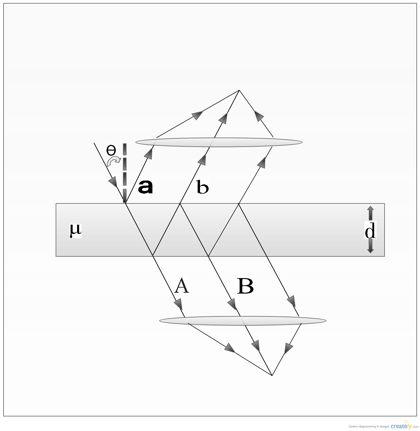
The diagram below represents the typical Fabry-Perot Interferometer:
According to G. Hernandez, there will be a phase lag between the waves due
to the difference in the lengths of the paths that they take through the
interferometer. The lag between waves A and B can be calculated as follows:
where ν is the frequency of the wave, μ is the
refractive index of the material between the two reflective surfaces,
d is the distance between the reflective surfaces and
θ is the angle of the incident light with respect to the
normal of the transmitting surface.
If μ d c-1 = t/2 , where t is the time for the
light ray
to transmit through the first layer, reflect off of the second, then
transmit through the first again, then it follows that:
If θ = π/2, then there is no phase lag(the light did not
transmit
or reflect, in fact it simply ran along the surface. Interestingly, the
phase lag increases as θ increases, until θ = 0.
At
that
point, waves A and B will be out of phase by a multiple of
the period, so they will be technically in phase once again.
To calculate the amplitude of each wave, one must know the reflection and
transmission coefficients of the surfaces.
I was confused as to where the exponential terms came from, so I decided
to learn more about superposition of wave functions.
The amplitude of any sinusoid function can be modelled by the following
functions:
The following Argand diagram in the complex plane reveals how they can be
incorporated into the complex amplitude of the wave, z:
So z can be expressed as:
In this case, we are considering the phase lag between waves, so:
When the reflected light is focused by the first lens, the total amplitude
is given by:
and for the transmitted light:
Note that:
χ represents the phase changes upon reflection on each surface
(when a wave reflects off of a fixed surface, the phase flips):
These amplitudes are complex and cannot be observed. By multiplying them
by their complex conjugate, we obtain the intensity of the wave.
Expressed in terms of the absorption scattering coefficient (because,
realistically, not all light is either reflected or transmitted) A,
where
It follows that:
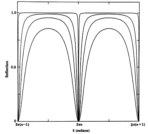
The plots below demonstrate the "transmitted and reflected radiation of a
Fabry-Perot Etalon as a function of the phase retardation of the beams for
various reflectivities. The values of the latter are: 0.98, 0.81, 0.65 and
0.45 for the narrowest to the widest profile":
It is important to take away from the diagrams above that a Fabry-Perot
interferometer with higher reflectivity on it's mirros is ideal. This is
demonstrated by the fact that at higher reflectivies, it is easier to
differentiate between lines that are close together--there is an increase
in spectral resolution. It is also interesting to note that, if A=0,
meaning that the reflective material of the mirrors does not absorb nor
scatter light, that
So, for all reflectivities R, in the absence of absorption and
scattering, the intensities of the transmitted and reflected light add to
unity. This simply means that the energy of the waves if conserved. This
is the result that I would always expect, but it is nice to check just
to make sure that I understand the physics system and how it conserves
energy.
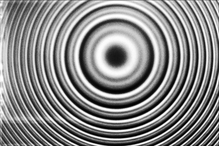
What kind of interference pattern should one expect to see from such an
interferometer? Due to the circular symmetry of the Fabry-Perot, one will
see an interference pattern of bright concentric rings, like the one
illustrated in the image below:
G. Hernandez explains that, for the case of transmission,
there will be maxima at which constructive interference occurs at specific
angles related to the phase lag between succesive transmitted waves:
where σ is the inverse wavelength, or wavenumber, given by:
It can be seen that a single wavenumber corresponds to multiple
interference maxima at specific angles givn by the equation above. The
difference in wavenumber between these successive maxima is known as the
free spectral range, and is given by the following:
where n0 is the central order of interference for
transmission ( the bright circle at the center of the interference
pattern ).
It is interesting to note that,
Which follows that,
So, the formula for the free spectral range of a Fabry-Perot
interferometer is the same as that for the beat frequency between
adjacent laser modes of a laser. It makes sense why this is the case,
because the two systems are very similar. In both, the frequencies of
light that are sustainable inside the cavity that get amplified can fit an
integer number of half-wavelengths between the two mirrors of said cavity.
It should be noted that this discovery disproves an assumption I made in a
much earlier journal entry a few months ago. Upon my derivation of the
beat frequency of a laser, I assumed that it would be the same, regardless
of the medium is was in, because I ended up with Δf = c / 2
l,
which has no factor related to the medium of the cavity. The reason for
this, is because I chose a particular medium without realizing it:
vaccum. I simply didn't incorporate the index of refraction into
the speed of light in a particular material, which was incorrect. The
speed of light in a given material with index of refraction n is
given by:
Transverse modes were a subject of one of the sub-topics of my report on
my laser modes
project. I discovered that some of Dr. Noe's past students did work on
creating these kind of modes as well.
The simplest transverse mode has a Gaussian intensity profile. Transverse
modes can be created by putting a thin obstacle in the lasing path (such
as a hair), or by slightly changing the
orientation of the output
coupler mirror. These patterns
can actually be modeled mathematically
if one multiplies the
Gaussian function that represents the 0-0 mode by a Hermite Polynomial.
Similar work was done by a former student of Dr. Noe named Justin Tian. In
his report, "Creating Higher-order Mode Laser Beams
with an Open Cavity Laser", he produced some quality transverse modes:
Interestingly enough, he used a different method than we did in order to
produce these modes. He used a scratched microscope slide instead of a
hair to obstruct the beam. In order to
minimize reflections he tilted the slide at the Brewster angle. This angle
can be calculated utilizing the Fresnel equation, if one knows the index
of refraction of air (1.00) and of the
glass slide (about 1.518):
θB = arctan(n2/n1)
I'm very excited to be back at Stony Brook for the summer. Being here for
research gives me a completely different feeling from being here during
the semester, mostly because I don't have all the stress when worrying
about homework and exams. I can focus my time on learning what I'm
interested in instead of focusing on a curriculum preset for me. Every day
I have the opportunity to learn from the many scientists and grad students
here.
We have already had the opportunity to attend two seminars given by
Professor Eden Figueroa's former colleagues back in Germany about their
experiments, after which he showed us around his lab. His experiment
greatly intrigued me. Eden is the leader of the Quantum Information
Technology group here at Stony Brook. They are aiming to develop the
fundamentals of Quantum Information Technology (as the tech is still in
its infancy), such as developing quantum memory technologies as well as
quantum transistors and gates with the use of cavity electromagnetically
induced transparency(EIT).
The main goal of Quantum Information Technology it to be able to create
systems in which information can be stored in the form of quantum states.
The unit of of information is the quibit which is a two-level system, but
can also be in a superposition of the two states (this is the main
difference between classical and quantum information systems).
This quantum information is stored in atoms which act as quantum nodes,
and is transmitted between nodes by photons. In order for the photons to
carry the information about the atoms quantum state the photon and atoms
must become entangled. That is one of Eden's goals, but first he must be
able to isolate the single entangled photon from the laser fields. This is
a very difficult
task because the laser produces millions of photons over a short period of
time. He is able to do this through the use of etalons, which are solid
cavities
consisting of highly reflective surfaces. If the etalons have the proper
finesse (q-factor, which is related to losses of the system and bandwidth)
and free-spectral range, all cavity modes except for one can be
suppressed. This technique can be used to isolate the single photon.
In order to create a quantum memory, so that the information carried in
the
quantum state can be stored for a later release on command. Eden uses the
technique of EIT in order to slow
down the light so he can store it within a rubidium cell; normally, the
cell would not be able to contain the light, as it would be opaque. This
proces involves tuning
two lasers to interact with three quantum states of the rubidium. This
creates a spectral window of transparency in the absorption frequency.
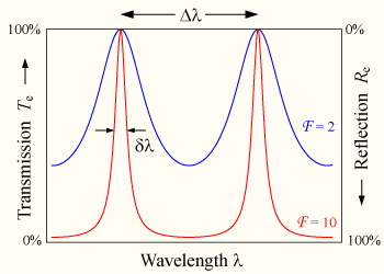
It can be seen below how the finesse of an etalon cavity affects the
allowed modes. Higher finesse (less losses) results in a narrower
line-width of
wavelength, which results in a smaller frequency range and thus less
allowed modes. The diagram shows that the "allowed" modes have high
transmission and low reflection. It would be ideal to make the peaks as
narrow as possible in order to allow virtually one mode, especially in the
case of Quantum Information experiments such as Eden's.
There haven't been recent updates to my journal because the focus of our project
has changed quite a few times. Measuring the coherence length of a laser is a very
difficult and delicate experiment that will run into numerous problems. It will
certainly not be a clean experiment to do, indeed the data may be impossible to
take properly because it is very difficult to tell where the two modes lose their
coherence because it is not easy to see when the fringe patterns completely
overlap or not. The geometry of the beam splitter actually leads to some fringe
like effects of the screen which can be confusing while trying to take these
measurements.
We decided to return to the roots of the project and look into the physics of
modes inside the laser's resonant cavity. We observed the frequency differences
(we like to call them "mode beats") on an oscilloscope. The actually frequency of
the modes cannot be seen on the oscilloscope because they are too high. One can
observe the differences between these differences, the "beats of beats", by
inscreasing the sweep speed. The number of these beats of beats oscillates with
time. This effect can be clearly seen on both the oscilloscope and the RA spectrum
analyzer, which plots the gain in dB (voltage) against the frequency instead of
time like the oscilloscope.
This phenomena is due to the changing environment inside the laser's optical
cavity. It can be described as the result of "mode pulling", which is similar to
mode competition. This mode pulling is the non-linear interactions between the
modes and the Neon gas (the gain medium in a Helium Neon laser). Modes are
electromangetic radiation, which is a changing electric field. If the electric
field which affects the atoms of the gain medium is changing, then their rate of
stimulated emission will be affected as well which in turn instigates the
development of the other modes. In this way, the modes indirectly affect eachother
through their direct interactions with the gain medium.
One can see this effect ont the spectrum analyzer when one particular beat
frequency is being analyzed. With time, it will change from being a single smooth
peak, to become greatly chaotic with several, seemingly random small peaks, only
to return to the smooth peak again. This process occurs over the course of a few
minutes. The smooth peak situation represents the state in which the interactions
between the modes and the gain medium cause the beat frequencies to have no
difference (no beat of beats), which the state in which the peak is broken up into
a rough, jagged, mountain-like peak represents the situation in which these "beats
of beats" exist because of the differences between the beat frequencies.
Interestingly enough, no one, not even Laser Sam (Mr. Goldwasser) is sure why, in
the "jagged peak" state of the beat frequency, why there appear to be too many
beats of beats, when one considers how many actual beats there are available to
interfere with one another. Perhaps this is the topic for a future project.
Although the jagged peak may seem random, it is not. If one watches several
oscillations, it can be seen that the same patterns arise again and again with
very little, perhaps no differences. It would be interesting to observe these
patterns with more or less combinations of beats of beats, by trying longer or
shorter lasers than the 44 cm HeNe which will support more or less modes.
The rate at which these oscillations occur is not constant with time. Dr. Noe left
the laser on over night, and returned to find that the oscillations had become
much slower. We believe that this is due to the "mode sweeping" phenomena, that
occurs as a result of the increasing temperature of the laser. When the laser is
first turned on, it will heat up, which will cause the cavity length to change. If
the cavity lenght changes, then the supported modes will change as well, and the
modes that fit under the gain curve will sweep back and forth, which will affect
the mode pulling phenomena, and thus the change in the beats of beats as well. The
rate of temperature change will decrease over time (it's a typical thermodynamic
system) as it approaches equilibrium, which means that the oscillations in the
changes of the beats of beats will become less frequent. It would be interesting
to see if the patterns in the jagged peak representing the beat of beats stays
constant over long periods of time, or changes due to this phenomena.
One misunderstanding that we had was whether the waves completely destructively
interfere after one coherence length. The key to understanding this is that modes
outside of the cavity are travelling, NOT standing waves. The waves do
destructively interfere copmletely after they travel one coherence length, but we
cannot see this because this point is traveling at the speed of light. The time it
takes for this to occur is
Where Lc is the coherence length of the laser, c is the
speed of light, and Δf is of course the mode
separation.
This means that the modes cancel out completely at a frequency of
This is not dependent on c, so we don't have to know the speed of
light accurately in the gain medium in which the light is moving in order to calculate this rate at
which the modes go dark.
My misconception about the origin of the fringe patterns was not entirely undone
as I had previously thought; I didn't really understand why the modes couldn't
interfere with eachother. Surely two different waves can still interfere with one
another even if they have different frequencies and thus different wavelengths. As
it turns out, the two modes (in the case of the short 10 cm Helium Neon laser) are
oppositely polarized; they have an orientation difference of about 90 degrees.
This is the reason that they are unable to interfere, construcvtively or
destructively with one another. Dr. Noe explained that this was due to "mode
competition" inside the laser. The fringe patterns do result from the modes
interfering with themselves, after the beam splitter splits each in to two plane
waves, they reflect off of the mirros and can come back at a slightly different
angle depending on the arm length difference (the difference in the distances that
the components of the separated beam travels). Fringes form where the plan waves
intersect one another.
I am still confused by this mode competition phenomena, however, so the confusion
has not been fully cleared up for me. According to the RP Photonics Encyclopedia,
this phenomenon can be described as follows: "In a situation with strong mode
competition (in the sense of strong overlap of mode intensity distributions),
which may occur, e.g., in a unidirectional ring laser, a single mode may be
excited in the steady state (? single-mode operation, single-frequency lasers):
the mode with the highest net gain will saturate the gain so that it exactly
balances its losses, and any other mode will then experience a negative net gain,
which causes its power to fade away." This means that the modes can limit
eachother through spatial overlap and through their interactions with the gain
medium. I'm still not entirely sure why this leads to the modes being oppositel
polarized however... perhaps the modes can limit eachother so that only certain
polarizations are allowed?
Our current project Idea involves measuring the coherence length of a laser. Our
interest clearly lies in understanding the concepts of lasers as resonant systems
and how the frequencies of light that can be amplified by a laser exist as modes
within the laser's optical cavity.
This idea can be easily understood through observation of a laser's gain curve.
This gain curve is the plot of gain in power vs. frequency of the light inside the
laser's cavity. The shape of this curve and what frequencies it covers depend on
the material that comprises the gain medium. The modes that are stable are the
ones that lie under the gain curve. As it turns out, if the lenght of the laser is
increased it can support more modes, and they will be closer together, so the beat
frequency between two modes will be smaller.
A short laser will generally have a more narrow gain curve and will thus support
less modes at any given time. Suppose we have a short laser of length 10cm or so
that will support either 1 or 2 modes at any given time (more on the number of
modes being amplified at any given time later). If the modes wavelenths differ by
λ/2, then the difference between the supported modes
underneath the gain
curve is Δf = c/2L, where c is the speed of light
and
L is the length of the
optical cavity.
In the case of two stable modes, after the modes leave the laser cavity, their
coherence will deacrease, and the fringe pattern seen on the screen will become
blurred. Two waves are said to be coherent if the realtion between their two
phases is constant.
The length of the cavity is equal to the coherence length, in the case of a short
laser that can support a maximum of two modes, (which can be
verified with the equation, Δf = c/2L, if one knows the width
of the gain curve of that laser).
In order to adjust the length between the laser and the screen, a Michelson Interferometer
can be used, which is comprised of a beam splitter that separates the laser beam into
two, one of which is reflected back by a moveable mirror, the other of which is
reflected by a fixed mirror back through the beam splitter onto a viewing screen
on which interference patterns can be observed. A misconception that I had was
that these fringe patterns were due to the different modes interfering with
eachother constructively and destructively, but it is actually due to the modes
interferring with themeselves after they are split and meet back at the
beamsplitter. The arm length can be adjusted to change the toal distance between
the laser and the viewing screen.
Since we still haven't decided on the exact topic of our project, I figured that
it would be a good idea to review the basic concepts of the general subject of
lasers. I picked up a book from the Math, Physics and Astronomy Library here at
Stony Brook Univeristy called Principles of Lasers. I was unable to take out the
book titled LASERS by Peter Milloni because it cannot be taken out of the library.
It is only up for two hour loans. I did some digging and found a book
titled Principles of Lasers, by Orazio Svelto from the Polytechnic
Institute of Milan, which is probably the next best thing. The
first chapter, titled Introductory Concepts, focuses on the general theory behind
"the laser idea".
The first section discusses spontaneous emission in general. In nature, Atoms will
tend to decay to lower energy levels. When the electrons orbiting the atom go
through this decay to the lower energy level, the energy must go somewhere because
energy must always be conserved. This energy will be radiated away in the form of
an electromagnetic wave. If the two energy levels are E2
(higher) and E1
(lower), then the frequency of this electromagnetic wave, or how many times the
electric and magnetic field components that comprise this wave oscillate per
second can be calculated as follows:
f = ( E2 - E1 )/ h
Where h is of course Planck's constant. It must be noted, however
that the energy
can also be released kinetically to surrounding atoms and molecules. It must be
noted that there is no definite phase relation between the separate atoms so the
wave can be emitted in any direction. This means that light emitted spontaneously
will be very incoherent. The rate of decay to due spontaneous emission can be
modeled as a differential equation:
(dN2/dt)sp =-A2,1 N2
Where N2 is the number of atoms per unit volume in level
two and A is the
spontaneous emission probability, or the Einstein A coefficient which depends on
the particular element and energy levels involved in the transition. The time that
the electron will stay in the upper energy level, or the spontaneous emission
lifetime, can be calculated by integrating the rate of decay formula above:
tsp =1/A2,1
The second section focuses on stimulated emission, which is at the heart ot the
laser's functionality. Incident electromagnetic radiation can cause an atom to
decay in energy, if and only if its frequency is equal to the atom's frequency.
This is very strange to me and I do not understand it. I can imagine it as
"knocking the electron down" because it has the same energy as it, but then why
would it not work if the incident photon has more energy? I need to learn more
about this, but I have the feeling that it requires knowledge of quantum
mechanics. Anyway, when the electron decays to the lower energy level equal to the
energy of the incident photon, it will then emit a photon of not only that same
energy, but also with the same phase as the incident radiaion. This must then be
why lasers are nearly monochromatic and very coherent.
The formula for the rate of decay due to stimulated emission is slightly
different than the rate of decay formula for spontaneous emission:
(dN2/dt)st = -W2,1 N2
Where W2,1 is the stimulated transition probability which
depends on the
particular transition and the intensity of the incident electromagnetic
wave:
W2,1 = σF
Where σ is the stimulated emission cross-section, and
F is
the photon flux
of the incident wave. This makes sense: if the area of atoms and/or the amount of
incident photons is larger, one would expect the transition to be more likely, and
the rate of decay should increase.
The third section focuses on absorption. This works oppositly to stimulated
emission. If an incident photon has more energy than an atom, it will increase the
atoms energy by an amount equal to its own, if there energies would sum to a
stable level. However, the probabilites of either stimulated emission and
absorption are equal. The formula for the rate of absorption is the same as that
for the rate of stimulated emission, except N2 is
replaced with the number of
atoms per unit volume in level one, N1. The stimulated
emission probability is
also the same and the transition cross section in this formula,
(dN1/dt)st =-W1,2 N1
The fourth section of this chapter final introduces the idea of a laser, that a
material with energy levels E1 and E2
and population densities of those energy
levels N1 and N2 will cause a change
in flux in a plane wave that passes through
it due to stimulated emission and absorption, given by:
dF=σF(N2 -N1)dz
This is very interesting. The material will behave as an amplifier if
N2 > N1
because (dF/dz)>0 and if N2 < N1 then
the material behaves as an absorber
because (dF/dz)<0. If the material is in thermal equilibrium, which
means no heat
is entering or leaving the material, then the ratio of the level populations can
be calculated as follows:
(N2/N1) = e(-E2 -
E1)/(kT)
Where k is Boltzmann's constant and T is the absolute
temperature of the
material. It should be noted that T will represent the kinetic
temperature
if and only if the material is also in thermodynamic equilibrium,
meaning that the total emission is equal to the total absorption. In
thermal equilibrium, N2 < N1 so the material
acts as an absorber. If
nonequilibrium is acheived for which N2 > N1
then the
material will act
as
an amplifier, in which case there is a population inversion, and the
material is considered to be "active".
LASER stands for Light Amplification by
Stimulated Emission of
Radaiation. The typical laser consists of a resonant cavity with
resonance
at the frequency of the transition of stimulated emission. The cavity is
enclosed by two higlhy reflective mirros so the plane electromagnetic wave
will reflect back and forth, getting amplified (increase in flux) each
time it passes through the active material. One mirro is made slightly
more transparent so an output can be achieved. The "lasing threshold" is
reached when the gain of the active material fully compensates for the
losses due to output coupling. The gain per pass in the active material is
given by:
Φoutput / Φinput
=e(σN2 - N1)l
where l is the length of the active material. The lasing threshold
will be
reached when:
R1 R2 e2σ(N2 - N1
) l = 1
Where R1 and R2 are the power
reflectivities of the mirros (if losses
are only due to transmission through the mirros because of their imperfect
reflectivity and not due to any other flaws of the cavity). The
critical inversion for the lasing threshold will be reached when:
(N2 - N1)c = -ln(R1
R2)/(2σL)
When this critical inversion and lasing threshold is reached the oscillations will
build up from the spontaneous emission. These spontaneously emitted photons along
the cavity axis will initiate the amplification process.
Most photodetectors aren't fast enough to measure the duration of ultrashort
pulses. One way to get around this difficulty is by using an interferometric
autocorrelation setup. This setup involves focusing a pulse from a mode-locked
laser with a collimating lens onto a retroreflector, so the light would be
reflected back in the same direction parallel but slightly displaced, so it could
then be put through a beam splitter. This beam splitter is a partially reflecting
mirror that splits the pulse into two separate pulses. The arm length of the
interferometer is chosen to be small so that the split pulses overlap and
constructively interfere. This arm length can be adjusted to vary the time delay
between the pulses, which will ultimately be used to estimate the duration of the
original. After this, the pulses propagate collinearly(in parallel) into a second
harmonic generation crystal. When pulses pass through these crystals they are
non-linearly polarized in such a way that the outgoing pulse has half the
wavelength of the ingoing pulse, and thus twice the frequency. This is a form of
sum frequency generation, a non-linear optical process, in which the pulses
polarity is changed in a non-linear fashion due to the electric field, which
typically occurs at high intensities. With a much higher frequency the amplitude
of the pulse will be much higher than the background noise, so its duration can be
more accurately estimated. The pulses will have the same polarity when they exit
the crystal. It is important to note that sum frequency generation conserves
energy, so the angular frequency of the outgoing pulse is simply the sum of the
angular frequencies of the combined photons, all multiplied by Max Plancks
constant divided by 2 (ℏ).
h/23=h/2(2+1)
The autocorrelation signal, or the average power, which is recorded by a
photodetector, can then be related to the time delay through the following
equation:
IM()=-+(E(t)+E(t-))22dt
The duration of the pulse can be estimated from the plot of the autocorrelation
signal by measuring its width. Characterizing ultrashort pulses has many uses,
such as determining the wavelength of the output light of a mode-locked laser.
Today Dr. Noé explained that a laser is in fact a resonant system. When
making a laser one cannot just have any size cavity. In order to create a resonant
system with the laser, the incident frequency of the light must match the cavity
mode, so a standing wave can form inside the cavity. The ends of the cavity must
be constructed of mirrors: one that is 95% reflective, so the laser light can
eventually escape, and one at the other end that is 100% reflective. Because of
this, what is called circulating power develops: when light makes its first go
around in the cavity, it reflects off the 95% reflective mirror, but some of it is
lost. Whats left reflects off the other mirror back to the 95% mirror, and some is
lost again, but even less than before, and then the process continues until the
incoming energy equals the outgoing energy(this is known as cavity buildup, which
occurs in all resonant systems). Dr. Noe explained that because of this, there is
always more power on the inside of the cavity than the output, but that power is
unattainable because one would have to interrupt the system to harness it.
Dr. Noé also taught me something about the polarization of light.
Unpolarized light, which is often encountered in daily life, is oscillating in
various directions. Light can be polarized with a polarizing filter, which only
lets light oscillating parallel to a certain plane in three-dimensional space pass
through. This is known as linear polarization. There are other kinds, along with
[such as?] circular polarization, which is particularly interesting. By rotating a
filter in front of linearly polarized light, Dr. Noe showed me that it was
possible to completely dim it. However, attempting to do the same with circularly
polarized light proved unsuccessful. In order to polarize circularly polarized
light, one must pass it through not just any ordinary filter, but a quarter-wave
plate. The construction of one requires a birefringent material, which refract
light differently depending on the orientation of the light passing through. Wave
plates shift the phases between two orthogonal components of the light wave. The
birefringent crystal is cut so that an ordinary and extraordinary axis form. Both
axes have a different index of refraction, so light components that travel along
each of them will have different speeds in the crystal, which results in a phase
difference when they exit the medium. In quarter-wave plates, the birefringence
and thickness of the crystal result in a phase shift of π/2, so that the
exiting light is elliptically polarized. If the axis of polarization is made so
that it makes a 45 degree angle with the ordinary and extraordinary axes, the
light will be circularly polarized. It is important to note that the crystal must
be cut into the plate so that the optical axis(the axis along which light
experiences no birefringence) is parallel to the plates surface, in order to form
the ordinary and extraordinary axes.
Savg = ( S · J )J /
Lavg = ( L · J ) J /
μ = -μB ( gℓ ( L · J )J /
< VM > = μB J(( L · J )J /
 The conclusion to this derivation was taken from Wikipedia
gj = 1 ± gs - 1 / 2ℓ + 1
Monday, June
24th, 2013
Wednesday, June 19th, 2013
Φ = 4 π ν μ d c-1 cos(θ)
Φ = 2 π ν t
cos(θ)
Ex: Amplitudes of sucessive waves reflected from plates (a,
b, etc.):
r1 , t12 r2
eiΦ , t12 r23
e2iΦ
x = r cos(θ) , y = r sin(θ)
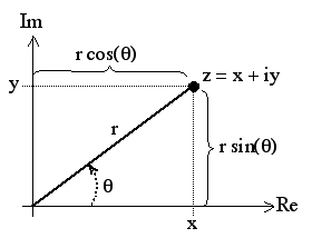
Above diagram obtained from daviddarling.info
z = x + i y = cos(θ) + i sin(θ) = eiθ
z = eiΦ
Ar(Φ) = r1 + t12
r2 eiΦ + ...
= [ ( 1 - eiΦ ( R + τ) ) R1/2 ] ( 1 - R
eiΦ)-1
At(Φ) = t1 t2 + t1
t2 r2 eiΦ + ... = τ ( 1 - R
eiΦ )-1
t1 t2 = τ
r1 = - r2
r12 = r22 = R
δ = Φ + 2χ
Yr(δ) = Ar(δ) Ar*(δ)
= R [ 1 - 2 ( R + τ ) cos(δ) + ( R + τ )2 ] [ 1 +
R2 - 2 R cosδ ]-1
Yt(δ) = At(δ) At*(δ)
= τ2 [ 1 + R2 - 2 R cos(δ) ]-1
R + τ + A = 1
Yr(δ) = R [ 1 + ( 1 - A )2 - 2 ( 1 - A )
cos(δ) ] [ 1 + R2 - 2 R cos(δ) ]-1
Yt(δ) = [ 1 - A (1 - R )-1 ]2 ( 1 -
R )2 ( 1 + R2 - 2 R cos(δ) )-1
= [ 1 - A ( 1 - R )-1 ]2 ( 1 - R ) ( 1 + R
)-1 ( 1 + 2 Σm=1 → m=∞
Rm cos(mδ)
= [ 1 - A ( 1 - R )-1 ]2 [ 1 + 4 R ( 1 - R
)-2 sin2(δ / 2) ]-1
= [ 1 - A ( 1 - R )-1 ]2 ( 1 - R ) ( 1 + R
)-1 2 ln(R-1) × Σn=-∞ →
n=∞ { [ ln ( R )-1
]2 + ( δ - 2 π n )2 }-1
![]()
Above images taken from "Fabry-Perot Interferometers"
Yr(δ) + Yt(δ) = R ( 2 - 2 cos(δ) )
( 1 + R2 - 2 R cos(δ)
)-1
+ ( 1 - R )2 ( 1 +
R2 - 2 R cos(δ) )-1
= [ R ( 2- 2cos(δ) ) + ( 1
-
R )2 ] ( 1 + R2 - 2 R cos(δ) )-1
= ( 1 + R2 - 2 R
cos(δ)) ( 1 +
R2 - 2 R
cos(δ)-1
= 1
Above image taken from Johnwalton on Wikimedia Commons
n = δ (2π)-1 = 2 μ d σ cosθ
σ = ν c-1 = λ-1
Δσ = ( 2 μ d )-1 = σ / n0
Δσ-1 = Δλ = c / Δf = 2 μ d
Δf = c / 2 μ d
v = c / n
Friday, June 14th, 2013

Thursday, June 13th, 2013

Monday, April 22nd, 2013
Thursday, March 28th, 2013
t = Lc / c = Δf / 2
fd = 2Δf
Tuesday, March 26th, 2013
Thursday, March 14th, 2013
Tuesday, March 12th, 2013
Tuesday, February 26th, 2013
Tuesday, February 12th, 2013