The operating modes of a physical system are formed by physical laws and boundary conditions. Consider a guitar string that is plucked. The physical law is the restoring force that tends to bring the string to its initial, straight position. The boundary conditions are that on either end of the string, the amplitude of the vibration must be zero. The superimposed waveforms that form the mode move with a fixed velocity that is dependant on the properties of the string, and have wavelengths equal to 2L/n, where L is the length of the string, and n is a positive integer. These are the modes of the system.
A propagating electromagnetic wave, which light is one type of, must satisfy the complex wave equation. This is:
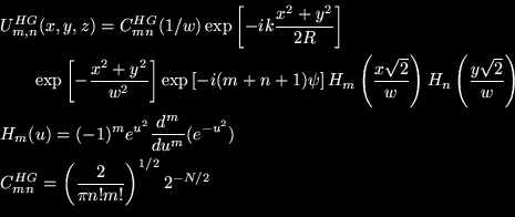
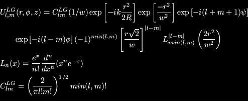
Similarly, lasers have modes. They have longitudinal and transverse modes. The transverse modes determine the intensity distributions on the cross-sections of the beam. The simplest mode is the Gaussian mode, which has a complex amplitude described by the cylindrical equation:
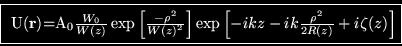
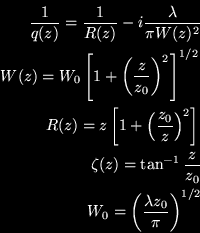
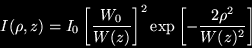
Since optical intensity is defined by  , we have:
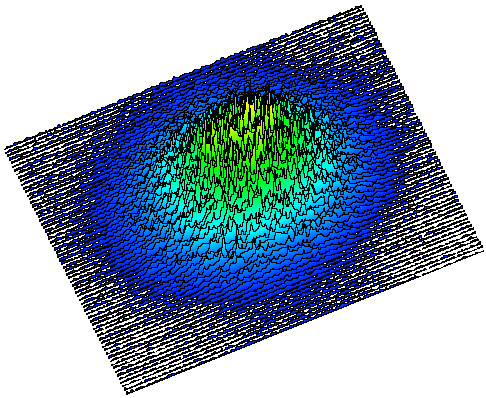
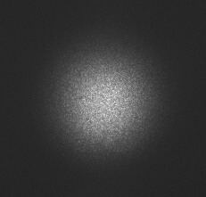
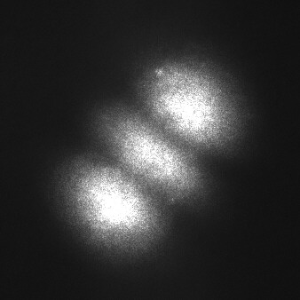
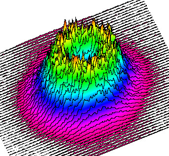
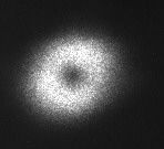
It appears as a central bright dot, as you can see above in the CCD image and Scion Image surface plot. Gaussian beams are usually the preferred output of most lasers, since they are easy to manipulate, are circularly symmetric, and usually have the greatest overall and concentrated intensity of all the transverse modes. They are stable as well, which means they retain their shape as they propagate.
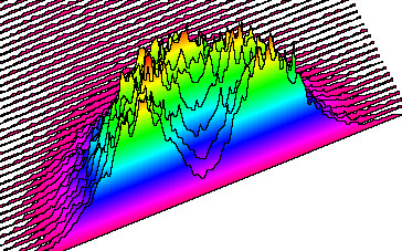
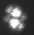
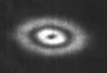
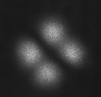
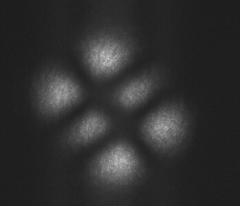
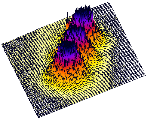 The Gaussian mode is a specific case of the more generalized Hermite-Gaussian (HG) modes. The HG modes are also referred to as Transverse Electro-Magnetic, or TEM. A TEM mode is described as TEMmn, where m and n are the indices of the mode. m refers to the number of intensity minima in the direction of the electric field oscillation, and n refers to the number of minima in the direction of the magnetic field oscillation. An HG mode appears to be a grid of dots, or blobs. At the right, you can see a CCD image and Scion Image surface plot of an HG02 mode. The Gaussian mode is a TEM00, or HG00 mode. The mathematical equation for its complex amplitude is:
 .
.
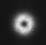
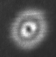
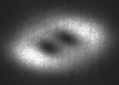
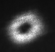
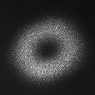
 LG modes, like the Gaussian mode, are circularly symmetric. However, all LG modes except LG00 are hollow. Their key feature is the presence of a screw phase dislocation, which means that is has orbital angular momentum. One cool application of this is the transfer of this momentum to a particle, making it spin. This screw phase dislocation is also the origin of the hollow center of an LG beam, since that type of phase dislocation appears as a dark spot. An LG mode is described by the equation (with symbols defined as they were for HG modes):
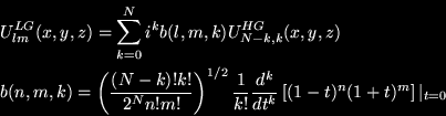
LG modes have a Guoy phase similar to HG modes, 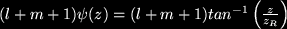 . They can also be expressed as the sum of HG modes of lower and equal order, by the relation:
Bessel beams are hollow (or bullseye in a special case) modes. Their most
important property is that they are "non-diffracting". This is in
quotations because only an ideal Bessel beam is really non-diffracting,
but this is experimentally impossible. To have a perfectly
non-diffracting Bessel mode, the beam must be infinitely wide. Still,
experimental approximations to Bessel beams have extremely low divergence,
and are therefore very useful in many applications, specifically in
optical tweezers, where an extremely tightly focused hollow beam is
optimal. Bessel Beams of arbitrary order can be generated by shining an LG mode on an axicon, which is a conical lens.
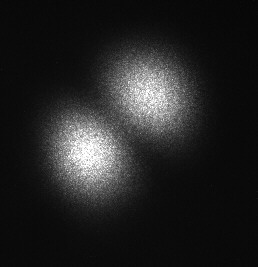
While proper misalignment of a laser cavity (with a Brewster window) can produce certain HG modes by geometric selection of portions of the gain material, there is a much easier way to control this for use in an astigmatic mode converter. As discussed below, an astigmatic mode converter needs an input mode rotated 45 degrees from the optical axis of the cylindrical lenses. While it is possible to mount the cylindrical lenses at 45 degrees to the table, that is difficult to align, which is a constant process. Instead, multimodes are used to generate 45 degree pure HG modes.
In general, there is competition between different transverse and longitudinal modes for use of the gain material in a laser cavity. Therefore, in general, there is more than one simultaneously oscillating transverse mode. The superposition of all these simultaneous modes is called a multimode. By selectively disabling parts of the gain medium, specific diagonal HG modes can be selected. This disabling is achieved by mounting a thin wire or human hair (about 25 microns across) at 45 degrees to the axis of the cylindrical lenses, and placing it on a translation stage between the Brewster window and the output coupler of the laser cavity. By translating it across the beam, an entire multimode, a smaller multimode, a single diagonal mode, or no mode at all can be selected from a single initial multimode.
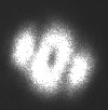
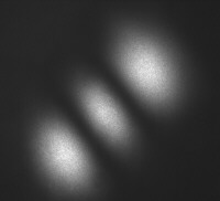
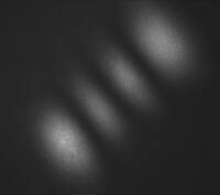
Intiutively, it would seem that a multimode with the greatest power output would contain the most single modes. To test this, I obtained four different multimodes, measured their power output with a ThorLabs DET110 photodetector and a multimeter, and tried to select as many single modes as possible. Each multimode was capable of producing single diagonal modes, and "bad" single diagonal modes, which were small superpositions that appear very similar to a specific single mode. Below, I show a chart of each of the four modes, its measured voltage from the photodetector, the power calculated as described below, and modes obtained. It is worth noting that a "bad" mode implies higher power and more potential mode choices than a normal mode, since it is a small superposition.
| Picture of Multimode | Voltage Produced (V) | Power (mW) | Achieved Modes HG(m,n) |
|---|---|---|---|
| 2.06 | 0.44 | 01, 02, 03, bad 12 |
| 1.59 | 0.34 | 02, bad 01 |
| 2.03 | 0.43 | 02, bad 11, bad 12 |
| 2.22 | 0.47 | 01, 02, 03, bad 01, bad 11, bad 12 |
As expected, multimodes of higher power contained mode single modes. However, this does not mean that one high-power multimode is the best source of single modes. Higher power modes are harder to select single modes from, since they have more modes to cut out before having just one. So some single modes were more easily obtained by selecting from relatively low-power multimodes.
The power output of the laser was calculated as follows. The particular photodetector has an associated curve of wavelength versus responsitivity, which is the ratio of the current from the photodetector to the power of the incident light that will produce that current. With this data, the power of a laser beam as measured by the photodetector will be voltage produced divided by the product of the responsitivity and the applied resistance, which was 10 kilo-ohms in my case. For HeNe light of 632.8 nm, the responsitivity of the DET110 detector is 0.42 A/W.
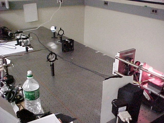
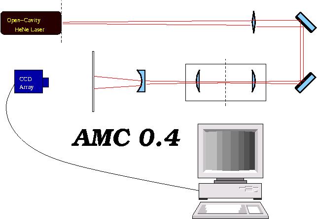
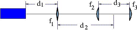
There are three main ways to generate an LG mode, with its screw phase dislocation. They are computer-generated holograms, intra-cavity circular absorbers, and astigmatic mode converters. Computer-generated holograms are impractical for high-power uses. Circular absorbers are not always practical, since laser cavities are often closed. Astigmatic mode converters are a very practical alternative. Although they require a source of a high-order HG mode, which usually requires cavity manipulation, it is possible to approximate them without opening or manipulating the laser cavity. One method is to take a Gaussian beam, split it, make them 180 degrees out of phase (as are the two "blobs" of an HG01 mode), and propagate them in the orientation of an HG01 mode, at a 45 degree rotation. But since I have access to an open-cavity HeNe laser, I did not have to do this. I simply adjusted the cavity to give a 45 degree rotated HG01 mode. At the left are two pictures of the astigmatic mode converter I am using.
 An astigmatic mode converter creates an LG beam by introducing a phase dislocation. This is achieved by exploiting the Guoy Phase
  , which is done by making the beam astigmatic in a confined region. This astigmatism is created by two cylindrical lenses aligned correctly, with equal focal lengths. For the so-called "
 /2" converter, named by the phase difference it introduces, the distance between the lenses must be
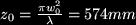
  . The other requirement is the mode-matching of the beam. First of all, the waist of the incident beam must occur halfway between the cylindrical lenses. Also, the Rayleigh range of the beam must be given by the formula:
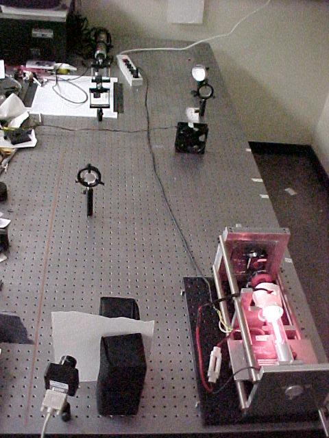
 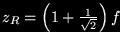 . On the left, you can see two pictures of the astigmatic mode converter in its current state.
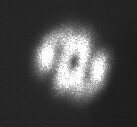
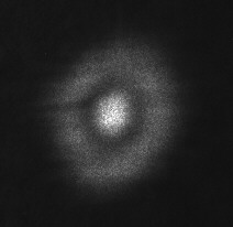
 So far, there have been four designs of the astigmatic mode converter, named AMC 0.1-0.4. AMC 0.1 was mathematically designed, but since one of the distances was negative, was scrapped. AMC 0.2 was the first to be actually built, and was able to produce 25% LG01 and 75% HG01 with an input HG01 beam. AMC 0.3 used new calculations, which were more correct, and was made with a mode-matching lens of greater focal length than AMC 0.2. In solving for d1, the first to be solved for, a quadratic with two real, positive roots was found. So AMC 0.3 was built twice, with calculations based on each root. Neither worked. After an elegant experiment to accurately determine the beam waist, I had new parameters for the calculations. So, AMC 0.4 was designed based on these new parameters, and is the current incarnation. It can achieve almost perfect LG beams, but only over a relatively small propagation distance. At left and right are some of the achieved LG modes. Below the calculations, you can see the full set of input HG and converted LG modes.

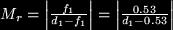
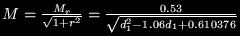
 /2 converter must be equal in focal length. The only ones I have access to have focal lengths
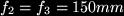 /2 converter is that the beam incident on the mode converter has a Rayleigh range
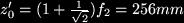

 and
and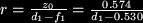

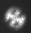
 Of course, this is all just theory. In experimental practicality, these numbers aren't precisely correct. The above parameters produce fairly elliptical beams, as opposed to the desired circular ones. At left and right, you can see the results of following the theoretical parameters exactly. Note that both are elliptical, and the one on the left still has traces of the input HG mode. This particular one is about 93% LG and 7% HG in composition. Below is a chart of all achieved input HG and converted LG modes. The nicer modes below used parameters of d1 = 1080mm, d2 = 890mm, and d3 = 270mm.
| HG(0,1) | HG(0,2) | HG(0,3) | HG(1,1) | HG(2,1) |
| 
| 
| 
| 
|
| LG(1,0) | LG(2,0) | LG(3,0) | LG(0,1) | LG(1,1) |
|
| 
| 
| 
|
|